
TM 5-3895-376-14&P
5-17. GOVERNOR ASSEMBLY MAINTENANCE INSTRUCTIONS - Continued
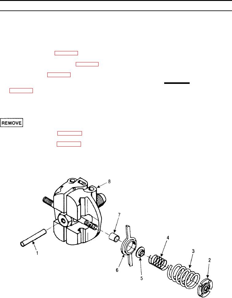
3.
Remove the governor pin (1).
in the range of 900 - 1100 rpm, while full load
speed is to be set at approximately 2850 rpm.
NOTE
9.
Repeat steps 1 through 8, until idle and full load
If governor does not have to be removed
speed are acceptable.
from the crankshaft, proceed with inspec-
tion and repair below. To remove gover-
10. Install the v-belt cover (Para. 4-24).
nor, proceed with steps 4 and 5.
11. If removed, install the gear cover (Para. 5-14).
4.
Secure the flywheel to prevent turning.
12. Service the engine (Para. 4-12).
CAUTION
13. Adjust the governor (speed) control shaft
The threads of the governor are left-
handed, size M12, and must be installed
with loctite. Considerable force may be
required to break the governor loose.
Damage to the governor may result if
turned in the wrong direction.
5.
Using a 14 mm deep socket, remove the gover-
1.
Remove the v-belt cover (Para. 4-24).
nor (8) by turning clockwise, ensuring that the
socket is fully engaged on the hex of the gover-
2.
Remove the gear cover (Para. 5-14).
nor.
5-49