
TM 5-3895-376-14&P
5-9. VALVES MAINTENANCE INSTRUCTIONS - Continued
4.
Install the cylinder head assembly (Para. 5-8).
WARNING
5.
Install and adjust rocker arms and push rods
Valve springs and collars are under
spring tension and can act as projec-
tiles when released and could cause se-
6.
Install fuel injector (Para. 5-4).
vere eye injury. Eye protection is
required.
7.
Connect fuel lines to the fuel injector (Para. 4-29).
d.
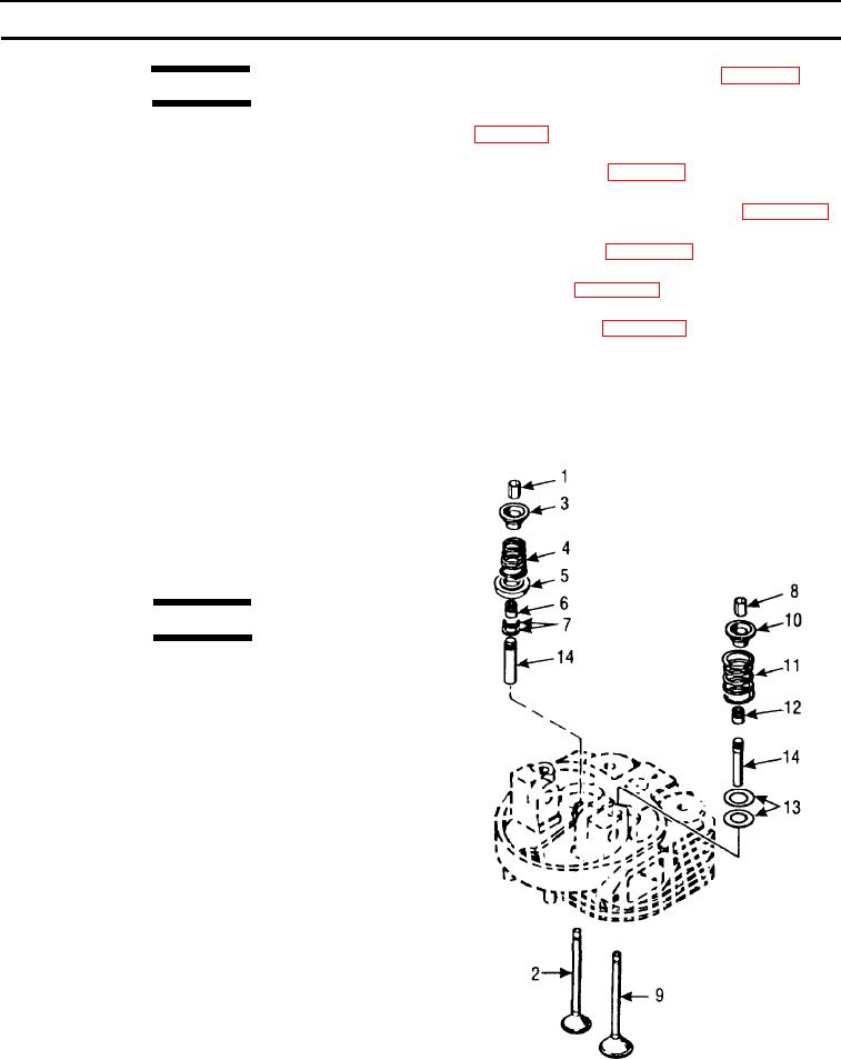
Install intake valve spring (11) and spring col-
8.
Install valve cover (Para. 4-33).
lar (10). Compress the spring and retainer us-
ing the valve spring lifter, sufficiently to allow
9.
Install muffler (Para. 4-31).
installation of the valve spring retainer (8). In-
ternal shoulder of the retainer halves must en-
10. Install air cleaner (Para. 4-27).
gage the notch of the valve stem, then
remove the valve spring lifter.
NOTE
Follow-on tasks include: Return compactor
2.
Install the exhaust valve (2) as follows:
to service.
a.
Install two washers (7), over the exhaust
valve guide.
b.
Install valve seal (6) on end of exhaust valve
guide.
c.
Install the exhaust valve (2), carefully feeding
stem through the valve seal (6).
WARNING
Valve springs and collars are under
spring tension and can act as projec-
tiles when released and could cause se-
vere eye injury. Eye protection is
required.
Install roto cap (5), exhaust valve spring (4) and
d.
spring collar (3). Ensure that large diameter end
of spring (4) is seated in the roto cap (5). Com-
press the spring and retainer using the valve
spring lifter, sufficiently to allow installation of the
valve spring retainer (1). Internal shoulder of the
retainer halves must engage the notch of the
valve stem, then remove the valve spring lifter.
3.
Check seating of valves in valve seats on bottom
of cylinder head. New valves must seat 0.098 -
0.102 in. (2.500 - 2.600 mm) below the bottom
face of the cylinder head. Remove a valve that
does not seat to this dimension, grind the valve
as necessary and reinstall.
5-22