
TM 5-3895-376-14&P
4-13. VIBRATOR MAINTENANCE INSTRUCTIONS - Continued
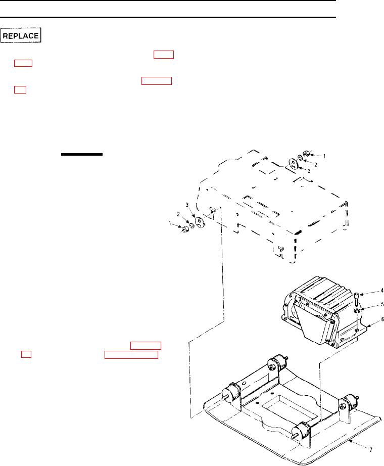
1 . If not already removed, remove the v-belt (Para.
2.
Disconnect the direction control cable (Para. 4-
3.
Remove four hex nuts (1), lockwashers (2), and
eccentrics (3).
CAUTION
The engine with engine base and at-
tached guide bar weigh approximately
250 pounds, select hoist with adequate
lifting capacity.
Attach a suitable hoist to lifting point on pro-
4
tection frame and lift the engine and engine
base from the base plate and set aside on
blocking
NOTE
Block unit so guide bar locking latch on
rear of engine base does not rest on floor
5.
Remove four socket head capscrews (4),
lockwashers (5) and vibrator assembly (6)
from the base plate (7).
NOTE
If control housing and shifter bolt (Para. 4-
19) are removed, refer to paragraph 4-19
for assembly instructions.
6.
Install the vibrator assembly (6) onto the
base plate (7), ensuring that the pulley
shaft end of the vibrator assembly is posi-
tioned away from the end of base plate with
large, 0.78 in. (20 mm) hole centered near
the edge.
7.
Secure the vibrator assembly to the base
plate (7) with four capscrews (4) and lock-
washers (5). Torque the capscrews (4) to
255 - 262 ft-lbs (345 - 355 Nm), with torque
wrench fitted with a 14 mm hex key driver.
4-11