
TM 5-3805-296-23-2
0093
Table 1. 0096 Fuel Level Sensor Diagnostic Code Continued.
093
CID FMI
TEST OR INSPECTION
CORRECTIVE ACTION
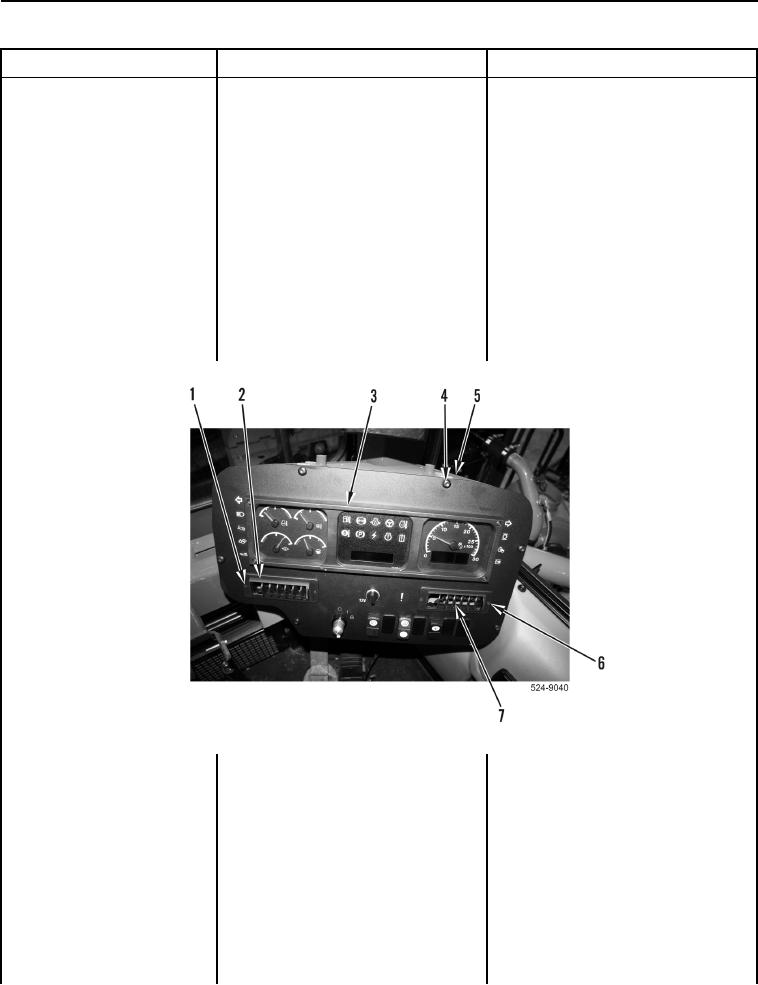
2. Remove two bolts
0096-03 Fuel Level Sensor
(Figure 7, Item 1) and left vent
Voltage Above Normal
(Figure 7, Item 2) from instrument
Continued
panel (Figure 7, Item 3).
3. Remove two bolts
(Figure 7, Item 6) and right vent
(Figure 7, Item 7) from instrument
panel (Figure 7, Item 3).
4. Remove six bolts (Figure 7, Item 4)
from instrument panel
(Figure 7, Item 3) and ROPS
(Figure 7, Item 5). Position
instrument panel to access
connector P-C18
(WP 0012, Figure 269).
Figure 7. Instrument Panel and Retaining Hardware.
0093
5. Disconnect connector P-C18
(WP 0012, Figure 269) from tractor
operator monitor.
6. Using digital multimeter
Resistance 5.0 Ohms or Less
(WP 0540), measure resistance
Replace tractor operator monitor
between connector P-C1
(WP 0506).
terminal 11 (WP 0012, Figure 253)
Proceed to Test Step 17.
and connector P-C18 terminal 9
Resistance Greater Than 5.0 Ohms
(WP 0012, Figure 269).
Replace dash wiring harness
(WP 0510).
Proceed to Test Step 17.