
TM 5-3805-296-23-2
0093
Table 1. 0096 Fuel Level Sensor Diagnostic Code Continued.
093
CID FMI
TEST OR INSPECTION
CORRECTIVE ACTION
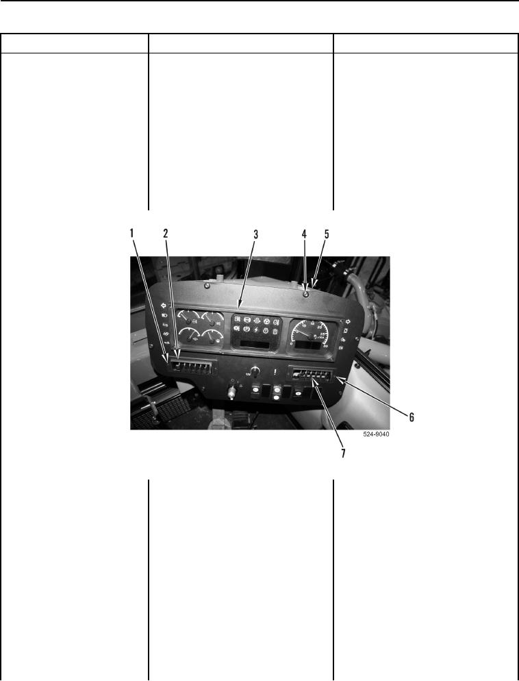
6. If removed, install instrument panel
0096-03 Fuel Level Sensor
(Figure 9, Item 3) with six bolts
Voltage Above Normal
(Figure 9, Item 4) on ROPS
Continued
(Figure 9, Item 5).
7. If removed, install right vent
(Figure 9, Item 7) with two bolts
(Figure 9, Item 6) on instrument
panel (Figure 9, Item 3).
8. If removed, install left vent
(Figure 9, Item 2) with two bolts
(Figure 9, Item 1) on instrument
panel (Figure 9, Item 3).
Figure 9. Instrument Panel and Retaining Hardware.
0093