TM 9-4940-568-34
5-141
(8)
From inside of drive housing (12), drive out
bushing (36).
(9)
After all items in Step (1) through (8) have
been removed, perform cleaning and
inspection procedures.
d.
Disassembly of Drive Shaft and Clutch Group.
NOTE
Disassembly of the drive shaft
and clutch group is not required
unless it is necessary to clean,
inspect, or replace one or more
parts of the group separately.
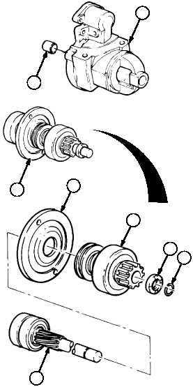
(1)
Position drive shaft and clutch group (25) on
work bench with internal gear end down.
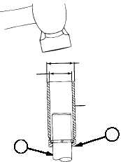
(2)
Using an open tube slightly larger than the
drive shaft (37), drive pinion stop (38)
toward clutch drive assembly (39) until it
clears two stop rings (40).
(3)
Using care not to scratch drive shaft (37),
pry two stop rings (40) out of shaft groove
and slide off end of drive shaft (37).
Discard stop rings.
(4)
Inspect edges of shaft groove for burrs that
may have been formed through repeated
cranking cycles. Burrs may make removal
of pinion stop (38) and clutch drive
assembly (39) difficult. If burrs are found,
use a suitable file to carefully remove burrs
only – not base metal. Thoroughly clean
away metal fillings.
(5)
Slide pinion stop (38) off drive shaft (37).
Discard pinion stop.
(6)
Remove clutch drive assembly (39) from
drive shaft (37).
(7)
Remove drive shaft support (41) from drive
shaft (37).
12
41
36
40
14.2 MM
(0.56 IN.) DIA
22 MM
(0.87 IN.) DIA
OPEN
TUBE
37
38
25