
TM 5-3805-296-23-5
0322
INSTALLATION CONTINUED
NOTE
Install hydraulic hoses as tagged and marked during removal.
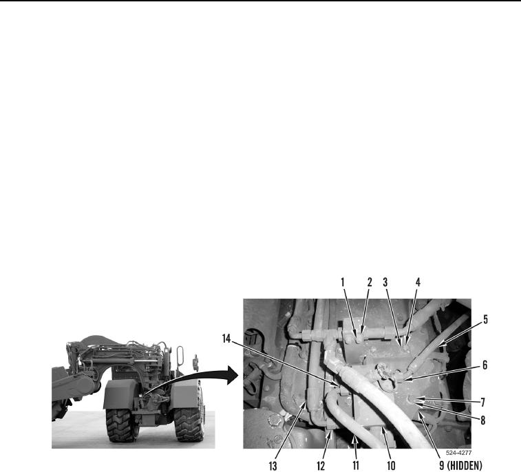
17. Install two spacers (Figure 12, Item 9), washers (Figure 12, Item 8), and bolts (Figure 12, Item 7) on machine.
18. Install three washers (Figure 12, Item 3) and nuts (Figure 12, Item 4) on machine.
19. Connect lines and tighten nuts (Figure 12, Items 6, 12, and 14) on pressure reducing valve assembly
(Figure 12, Item 8).
20. Install hydraulic hose (Figure 12, Item 13) on implement pilot solenoid pressure reducing valve assembly
(Figure 12, Item 10), tighten tube nut (Figure 12, Item 12).
21. Install hydraulic hose (Figure 12, Item 11) on implement pilot solenoid pressure reducing valve assembly
(Figure 12, Item 10), tighten tube nut (Figure 12, Item 14).
22. Install hydraulic hose (Figure 12, Item 5) on implement pilot solenoid pressure reducing valve assembly
(Figure 12, Item 10), tighten tube nut (Figure 12, Item 6).
23. Install two washers (Figure 12, Item 2) and bolts (Figure 12, Item 1) on machine.
Figure 12. Rear of Transmission.
0322
END OF TASK
FOLLOW-ON TASKS
000322
Verify correct operation of machine (TM 5-3805-296-10).
END OF TASK
END OF WORK PACKAGE
0322-13/(14 blank)