
TM 5-3805-296-23-5
0323
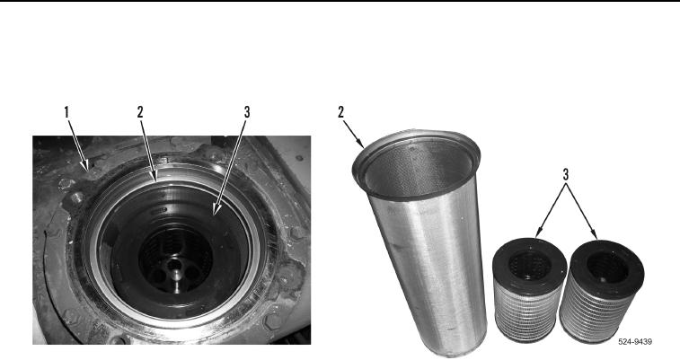
REMOVAL CONTINUED
3. Remove screen (Figure 2, Item 2) and two filters (Figure 2, Item 3) from hydraulic tank (Figure 2, Item 1).
4. Remove two filters (Figure 2, Item 3) from screen (Figure 2, Item 2). Discard filters.
Figure 2. Screen and Filters.
0323
END OF TASK
CLEANING AND INSPECTION
000323
Clean and inspect all components IAW Mechanical General Maintenance Instructions (WP 0539).
END OF TASK
INSTALLATION
000323
1. Install two new filters (Figure 2, Item 3) in screen (Figure 2, Item 2).
2. Install screen (Figure 2, Item 2) and two filters (Figure 2, Item 3) in hydraulic tank (Figure 2, Item 1).