
TM 5-3805-296-23-5
0297
REMOVAL CONTINUED
NOTE
Tag and mark hoses to aid in installation.
Cap and plug hoses and fittings to prevent contamination.
8. Loosen tube nut (Figure 2, Item 3) and remove hose (Figure 3, Item 1) from fitting (Figure 3, Item 4) on steering
control valve (Figure 3, Item 15).
9. Remove O-ring (Figure 2, Item 2) from fitting (Figure 3, Item 4). Discard O-ring.
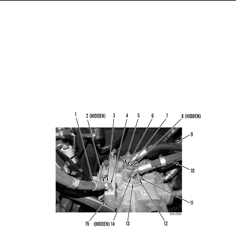
10. Remove four bolts (Figure 3, Item 5), washers (Figure 3, Item 6), two flange halves (Figure 3, Item 7), and
hydraulic hose (Figure 3, Item 9) from steering control valve (Figure 3, Item 15).
11. Remove O-ring (Figure 3, Item 8) from hydraulic hose (Figure 3, Item 9). Discard O-ring.
12. Remove four bolts (Figure 3, Item 11), washers (Figure 3, Item 12), two flange halves (Figure 3, Item 13), and
hydraulic hose (Figure 3, Item 10) from steering control valve (Figure 3, Item 15).
13. Remove O-ring (Figure 3, Item 14) from hydraulic hose (Figure 3, Item 10). Discard O-ring.
Figure 3. Hoses.
0297