
TM 5-3805-296-23-5
0296
INSTALLATION CONTINUED
NOTE
Route chain hoist about wheel on tire and wheel assembly.
6. Install sling (Figure 5, Item 2) on hand hold (Figure 5, Item 1).
7. Install sling (Figure 5, Item 4) on front fender bracket (Figure 5, Item 5).
8. Using assistance, install chain hoist (Figure 5, Item 3) on two slings (Figure 5, Items 2 and 4).
9. Using assistance, remove fork attachment from tire and wheel assembly (Figure 5, Item 6).
Figure 5. Chain Hoist and Sling.
0296
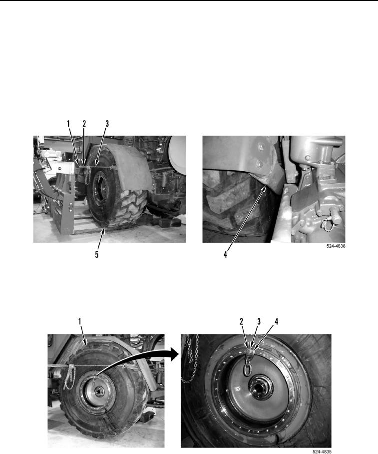
10. Remove bolt (Figure 6, Item 2), washer (Figure 6, Item 3), and lifting link (Figure 6, Item 4) from tire and wheel
assembly (Figure 6, Item 1).
Figure 6. Lifting Link.
0296
END OF TASK