Home
Download PDF
Order CD-ROM
Order in Print
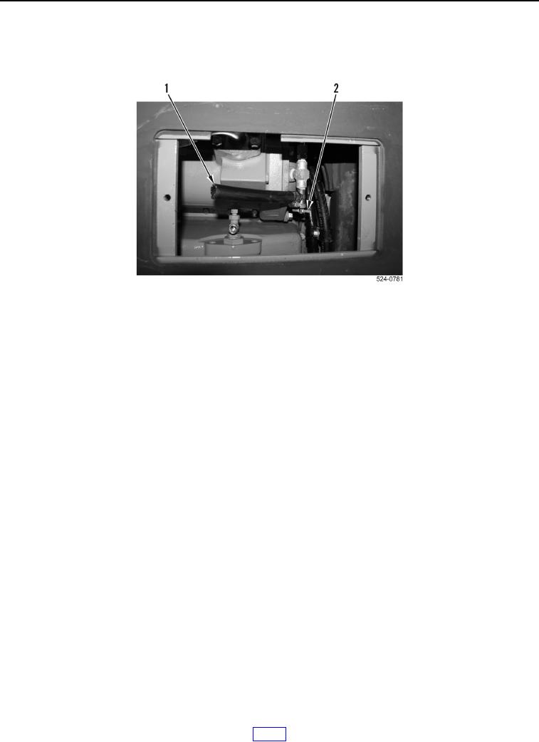
Figure 3. Cooling System Drain Valve.
COOLING SYSTEM SERVICE - Continued
Field Maintenance Manual For Military 621G Scraper -4
Page Navigation
503
504
505
506
507
508
509
510
511
512
513
TM
5-3805-296-23-4
0256
DRAINING
AND
FLUSHING
PROCEDURE
CONTINUED
10.
Install
access
cover
(Figure
4,
Item
2),
two
washers
(Figure
4,
Item
4),
and
bolts
(Figure
4,
Item
3) on
crankcase
guard
(Figure
4,
Item
1).
Figure 4.
Cooling
System
Drain
Valve.
0256
0256-5