
TM 5-3805-296-23-4
0256
DRAINING AND FLUSHING PROCEDURE CONTINUED
NOTE
Care must be taken to ensure that fluids are contained during performance of inspection,
maintenance, testing, adjusting and repair of the product. Be prepared to collect the fluid
with suitable containers before opening any compartment or disassembling any
component containing fluids.
Cooling system capacity is 19 gal. (72 L).
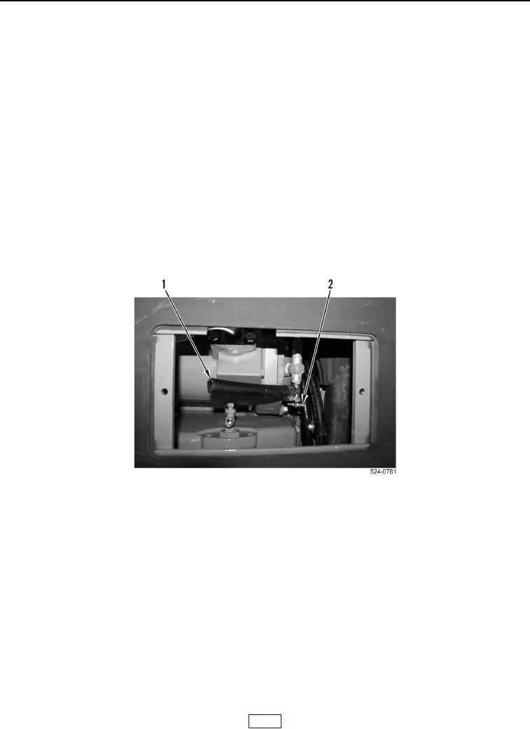
3. Position drain pan under coolant drain hose (Figure 3, Item 1).
4. Open coolant drain valve (Figure 3, Item 2). Allow coolant to drain into a suitable container.
5. Close coolant drain valve (Figure 3, Item 2). Fill cooling system with water.
6. Start engine (TM 5-3805-296-10). Run engine for 90 minutes.
7. Stop engine (TM 5-3805-296-10). Open coolant drain valve (Figure 3, Item 2) and drain water into a suitable
container.
8. Continue flushing system until draining water is clear.
9. Close coolant drain valve (Figure 3, Item 2).
Figure 3. Cooling System Drain Valve.
0256