• Home
  • Download PDF
  • Order CD-ROM
  • Order in Print
Figure 1. Cooling System Cap.
Figure 3. Cooling System Drain Valve.

Field Maintenance Manual For Military 621G Scraper -4 Page Navigation
  501    502    503    504    505  506  507    508    509    510    511  
img
.
TM 5-3805-296-23-4
0256
DRAINING AND FLUSHING PROCEDURE CONTINUED
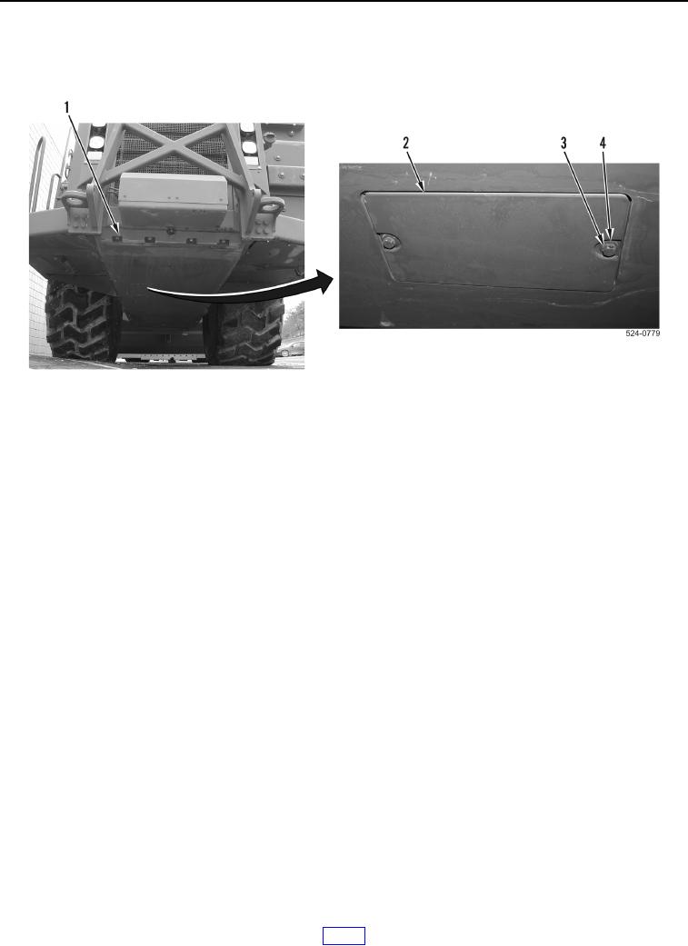
2. Remove two bolts (Figure 2, Item 3), washers (Figure 2, Item 4), and access panel (Figure 2, Item 2). Set
access panel (Figure 2, Item 2) aside.
Figure 2. Access Cover Removal.
0256
0256-3


Privacy Statement
Press Release
Contact

© Copyright Integrated Publishing, Inc.. All Rights Reserved.