
TM 5-3805-296-23-4
0238
INSTALLATION
000238
NOTE
Remove all plugs and caps from hydraulic hoses and fittings.
Refer to removal for elbow fitting orientation.
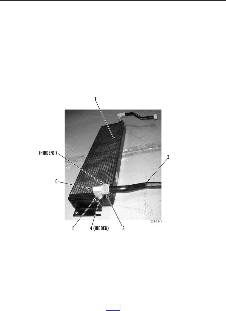
1. Install two new O-rings (Figure 5, Item 4), elbow fittings (Figure 5, Item 6) and tighten jam nuts
(Figure 5, Item 5) on hydraulic oil cooler (Figure 5, Item 1).
NOTE
Refer to removal for tube orientation.
2. Install two new O-rings (Figure 5, Item 7), tubes (Figure 5, Item 2) and tighten tube nuts (Figure 5, Item 3) on
elbow fittings (Figure 5, Item 6).
Figure 5. Hydraulic Oil Cooler Tubes.
0238