
TM 5-3805-296-23-4
0238
INSTALLATION CONTINUED
NOTE
Install P-clamp as noted during removal.
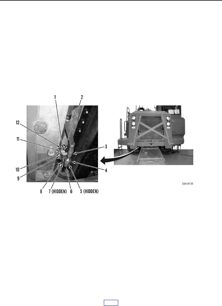
5. Install P-clamp (Figure 7, Item 9), washer (Figure 7, Item 10), bolt (Figure 7, Item 11), washer (Figure 7, Item 1)
and nut (Figure 7, Item 2) on machine.
NOTE
6. Refer to removal for elbow fitting orientation.Install new O-ring (Figure 7, Item 7), elbow fitting (Figure 7, Item
6) and tighten tube nut (Figure 7, Item 8) on hydraulic oil cooler (Figure 7, Item 12).
7. Install new O-ring (Figure 7, Item 5), hose (Figure 7, Item 3) and tighten tube nut (Figure 7, Item 4) on elbow
fitting (Figure 7, Item 6).
Figure 7. Hydraulic Oil Cooler Hose.
0238