
TM 5-3805-296-23-2
0098
Table 1. 0324 Action Lamp Diagnostic Codes Continued.
098
CID FMI
TEST OR INSPECTION
CORRECTIVE ACTION
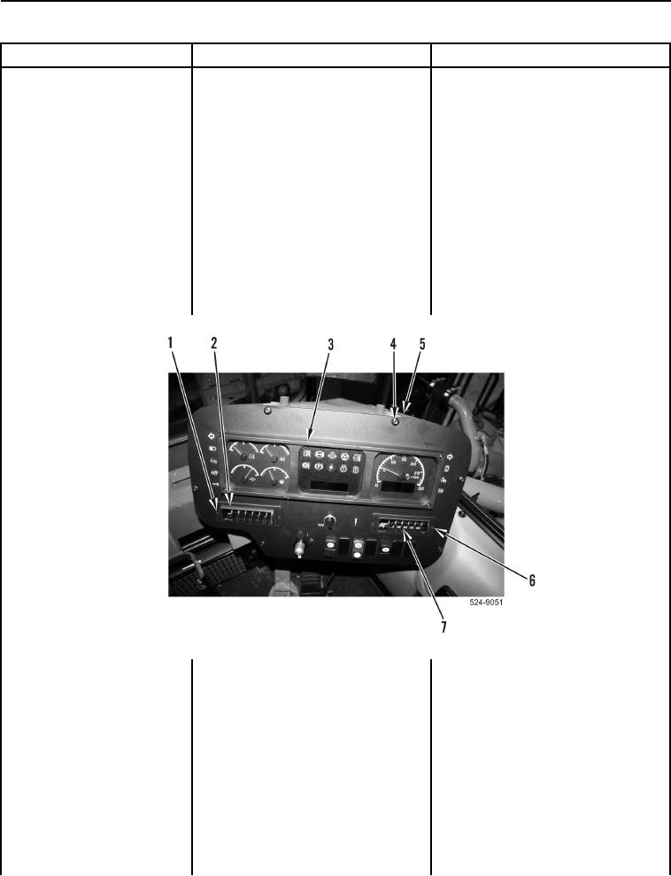
3. Remove two bolts
0324-06 Warning Lamp
(Figure 8, Item 1) and left vent
Short to Ground
(Figure 8, Item 2) from instrument
Continued
panel (Figure 8, Item 3).
4. Remove two bolts
(Figure 8, Item 6) and right vent
(Figure 8, Item 7) from instrument
panel (Figure 8, Item 3).
5. Remove six bolts (Figure 8, Item 4)
from instrument panel
(Figure 8, Item 3) and ROPS
(Figure 8, Item 5). Position
instrument panel to access
connector P-C18
(WP 0012, Figure 269).
Figure 8. Instrument Panel and Retaining Hardware.
0098