
TM 5-3805-296-23-2
0094
Table 1. 0177 Transmission Oil Temperature Sensor Diagnostic Code - Continued.
0094
CID FMI
TEST OR INSPECTION
CORRECTIVE ACTION
0177-08 Transmission Oil
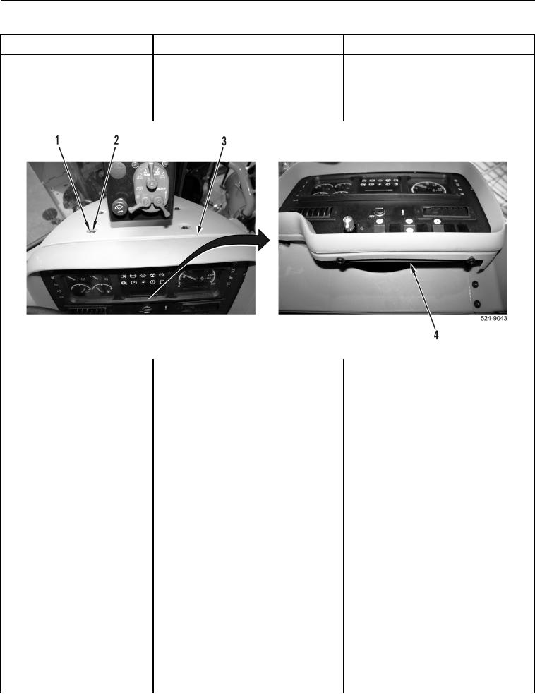
6. Install instrument panel cover
Temperature Sensor
(Figure 6, Item 3) with six washers
Abnormal Frequency, Pulse
(Figure 6, Item 2) and bolts
Width, or Period
(Figure 6, Item 1) on ROPS
Continued
(Figure 6, Item 4).
Figure 6. Instrument Panel Cover and Retaining Hardware.
0094
7. Install lower and upper plenum on
ROPS (WP 0504).
8. Install crankcase guard
(WP 0374).
Test Step 7. Test Engine Interface
Wiring Harness for High Resistance
or Open.
1. Turn ignition switch and battery
disconnect switch to OFF position
(TM 5-3805-296-10).
2. Disconnect connector W-C16
(WP 0012, Figure 87) from
connector CL-C3
(WP 0012, Figure 86).
3. Using digital multimeter
Resistance 5.0 Ohms or Less
(WP 0540), measure resistance
Proceed to Test Step 8.
between connector CL-C13
Resistance Greater Than 5.0 Ohms
terminal A (WP 0012, Figure 59)
Replace engine interface wiring
and connector CL-C3 terminal 7
harness (WP 0211).
(WP 0012, Figure 86).
Proceed to Test Step 16.