TM 9-4940-568-34
3-38
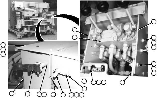
3-11. THREE FUNCTION CONTROL VALVE MOUNTING BRACKET REPLACEMENT
THIS TASK COVERS:
a. Removal
b. Installation
INITIAL SETUP
Tools
Tool Kit, General Mechanic’s
(Item 67, Appendix F)
Materials/Parts
Lockwasher (4) (Item 44, Appendix E)
Lockwasher (8) (Item 45, Appendix E)
Lockwasher (6) (Item 47, Appendix E)
Lockwasher (2) (Item 46, Appendix E)
Equipment Condition
FRS unloaded, (TM 9-4940-568-10).
a.
Removal
(1) Remove two nuts (1), lockwashers (2),
spacer plate (3), anchor bracket (4) and
screws (5) from cover (6). Discard
lockwashers.
(2) Remove screw (7), lockwasher (8) and
rubber latch (9) from mounting bracket
(10). Discard lockwasher.
(3) Repeat Steps (1) and (2) for other side
of control valve.
(4) Remove four screws (11), lockwashers
(12), washers (13) and cover (6) from
mounting brackets (10 and 14). Discard
lockwashers.
(5) Support valve manifold (15), remove
four screws (16), lockwashers (17) and
washers (18) from mounting brackets
(10 and 14). Discard lockwashers.
(6) Remove three screws (19), lockwashers
(20), washers (21), and mounting
bracket (10) from base (22). Discard
lockwashers.
(6) Remove three screws (23), lockwashers
(24), washers (25), and mounting
bracket (14) from base (22). Discard
lockwashers.
11
12
13
10
23
14
22
24
25
1
2
3
4
5
6
7
8
17
18
16
15
9
22
10
19
20
21