TM 9-4940-568-34
3-33
3-10. OUTRIGGER BEAM MAINTENANCE
THIS TASK COVERS:
a. Removal
b. Installation
INITIAL SETUP
Tools
Tool Kit, General Mechanic’s
(Item 67, Appendix F)
Materials/Parts
Sealing compound (Item 29, Appendix B)
Packing, preformed (4) (Item 112, Appendix
E)
Shim (A/R) (Item 164, Appendix E)
Shim (A/R) (Item 165, Appendix E)
Shim (A/R) (Item 166, Appendix E)
Shim (A/R) (Item 167, Appendix E)
Shim (A/R) (Item 168, Appendix E)
Shim (A/R) (Item 169, Appendix E)
Shim (A/R) (Item 170, Appendix E)
Materials/Parts Continued
Shim (A/R) (Item 171, Appendix E)
Shim (A/R) (Item 172, Appendix E)
Shim (A/R) (Item 173, Appendix E)
Shim (A/R) (Item 174, Appendix E)
Shim (A/R) (Item 175, Appendix E)
Personnel Required
1 Assistant
Equipment Condition
FRS unloaded, (TM 9-4940-568-10).
Jack cylinder removed, (para 3-9).
Special Environmental Conditions
Cleanliness is extremely important when working
on hydraulic equipment. Clean all parts before
disassembly and work in a clean area.
a.
Removal
NOTE
This procedure applies to both
right and left outrigger beams,
right shown.
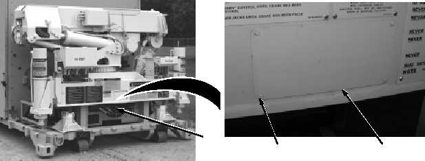
(1) Place drain pan under access hole at
the center of the base (1).
(2) Remove four screws (2) and cover (3).
1
2
3


