TM 9-4940-568-34
3-39
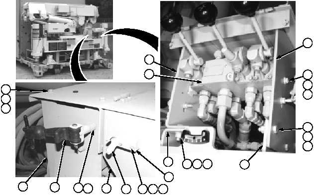
b. Installation
(1) Install mounting bracket (14) on base
(22)
using
three
screws
(23),
lockwashers (24), and washers (25).
(2) Install mounting bracket (10) on base
(22)
using
three
screws
(19),
lockwashers (20), and washers (21).
(3) Support valve manifold (15), install four
screws (16), lockwashers (17) and
washers (18) on mounting brackets (10
and 14).
(4) Install cover (6) on mounting brackets
(10 and 14) using four washers (13),
lockwashers (12), and screws (11).
(5) Install rubber latch (9) on mounting
bracket (10) using lockwasher (8) and
screw (7).
(6) Install spacer plate (3) and anchor
bracket (4) on cover (6) using two
screws (5), lockwashers (2) and nuts (1).
(7) Repeat Steps (5) and (6) for other side
of control valve.
END OF TASK
11
12
13
10
23
14
22
24
25
1
2
3
4
5
6
7
8
17
18
16
15
9
22
10
19
20
21