
TM 5-3895-376-14&P
4-21. TRANSPORT DOLLY MAINTENANCE INSTRUCTIONS
This task covers.
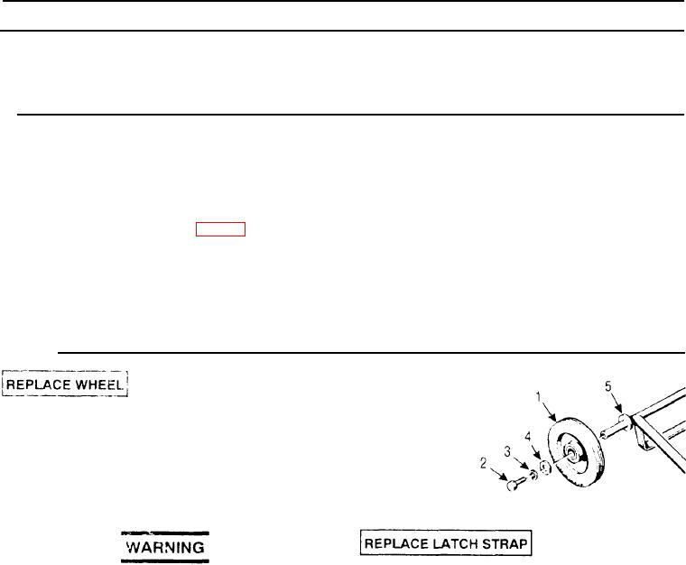
a. Replace Wheel
c. Replace Axle Frame
b. Replace Latch Strap
INITIAL SETUP
Tools
Equipment Condition
Tool Kit, General Mechanic's
Compactor set on level surface.
Engine off
Materials/Parts
General Safety Instructions
Solvent, Dry Cleaning, item 9, Appx E
Locknut. M10 (1)
Observe all WARNINGS and CAUTIONS
Lockwasher, MB (4)
Pushing, Plastic (2;
Locknut. M6 (2)
1
To replace a wheel (1), proceed as follows.
a
Remove capscrew (2), lockwasher (3) and
flat washer (4), that secure the wheel to, be re-
removed.
b. Slide wheel from the axle frame (5).
2.
Replace latch strap (6) and support bracket (7)
P-D-660, Type III, is moderally toxic to
as follows:
the skin, eyes and respiraton, ract;
avoid prolonged exposure. Skin and
a.
Release latch strap (6) and lower the trans-
eye protection is required. Good ventila-
port dolly to the ground.
tion is required. Do not use near open
flame or excessive heat. Flash point is
b
Remove Iocknut (8) and latch strap (6).
200 degrees F (93.3 degrees C).
C
Pull capscrew (9) from rubber spring ele-
c. Clean axle surface with a cloth dampened
ment (19) and remove flat washer (10)
with cleaning solvent and dry thoroughly.
d
Remove wingnut (11), flat washer (12) and
d
Slide replacement wheel (1) onto the axle
wrench (13).
frame (5)
e.
Remove two nuts (14), lockwashers (15),
e. Secure with flat washer (4), lockwasher (3)
capscrews (16, 17), flat washers (18) and
and Capscrew (2). Tighten capscrew securely.
bracket (7).
f
Replace other wheel in same manner.
4-32