
Basic Engine
The piston pin bore of a connecting rod and the
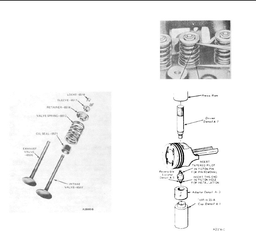
3. Install the value spring assembly over the value.
diameter of the piston pin must be within specifications. Refer
Install the spring retainer and sleeve.
to specification.
4. Compress the spring and install the retainer locks
(Figure 60).
5. Measure the assembled height of the value spring
from the surface of the cylinder head spring pad to
the underside of the spring retainer with dividers
(Figure 62).
6. Check the dividers against a scale. If the assembled
height is greater than specifications, install the
necessary 0.030 inch thick spacers (s) between the
cylinder head spring pad and the valve spring to bring
the assembled height to the recommended
dimension. Do not install spacers unless necessary.
Use of excess spears will result in over stressing the
valve springs and overloading the camshaft lobes
FIG 62 Checking Valve Spring Assembled Height
which would lead to spring breakage and worn
camshaft lobes.
FIG 61 Typical Valve Assembly
PISTON AND CONNECTING ROD
Disassembly
1. Remove the bearing inserts from the connecting rod
FIG 63 Removing or Installing Piston Pin
and cap.
2. Mark the piston and pins to assure assembly with the
1. Apply a light coat of engine oil to all parts. Assemble
same rod and installation in the same cylinder from
the piston to the connecting rod with the oil squirt
which there were removed.
hole in the connecting rod and the indentation in the
3. Using an arbor press and the tool shown in Figure 63.
piston dome positioned as shown in Figure 54.
Press the piston pin from the piston and connecting
2. Start the piston pin in the piston and connecting rod
rod, Remove the piston rings.
(this may require a very light tap with a mallet). Using
Assembly
an arbor press. press the piston pin through the
The piston, connecting rod and related parts are
piston and connecting rod until the pin is centered In
shown in Figure 64. Check the fit of a new piston in the
the piston (Figure 63).
cylinder bore before assembling the piston and piston pin to
3 Check the end gap and spacing (Figure 57) of all piston
the connecting rod. Refer to Page 1-13 for fitting pistons
rings. They must be within specifications.
procedure
4. Follow the manufacturer's instructions (included with
the piston ring package) and install the piston rings.
1-30