
Basic Engine
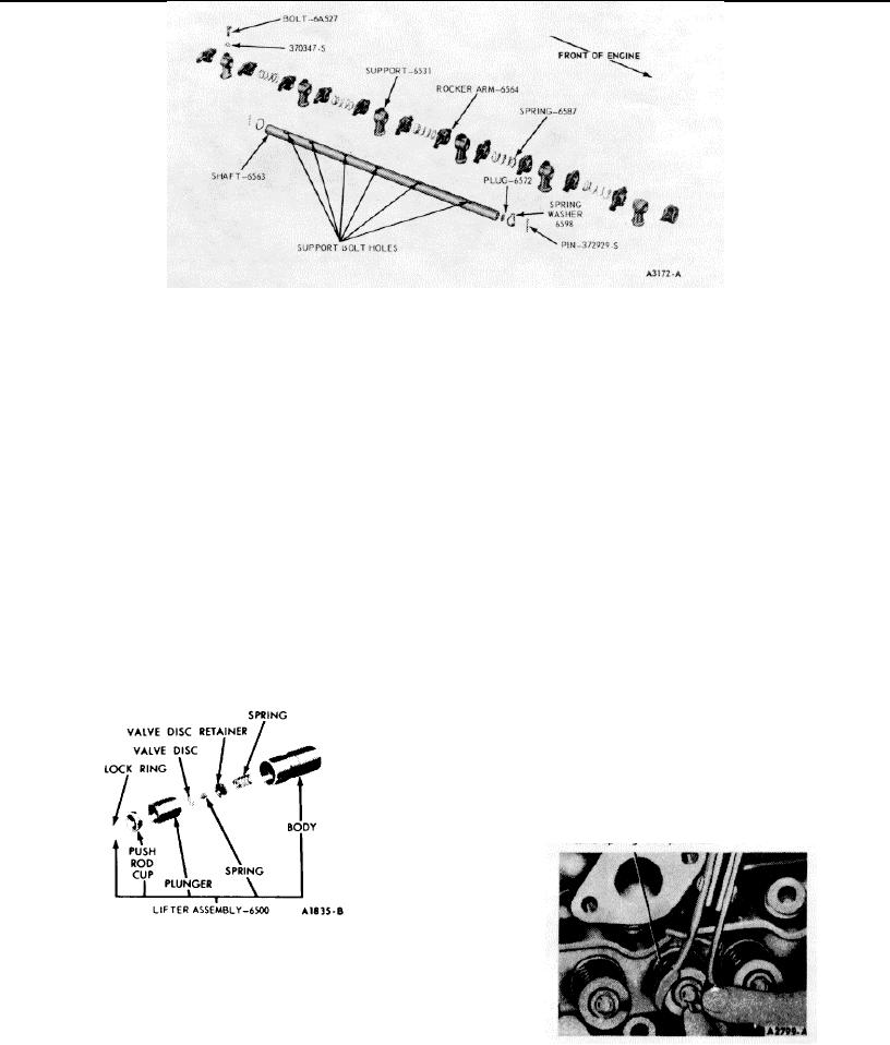
FIG 58 Valve Rocker Arm Shaft Assembly
5. Place the push rod seat in the plunger.
3. Install the spring washer and pin on one end of the
6. Depress the plunger and position the closed end of
shaft.
the lock ring in the lifter body groove. Release the
4. Install the valve rocker arms, supports, and springs in
plunger; then depress it again to fully seat the lock
the order shown in Figure 58. Be sure the oil holes in
ring.
the shaft are facing downward.
Complete the
assembly by installing the remaining spring washer
CYLINDER HEAD
and pin.
Disassembly
VALVE LIFTER HYDRAULIC
1. Remove deposits from the combustion chambers and
Each valve lifter is a matched assembly; therefore,
valve heads with a scraper and a wire brush before
the parts are not interchangeable. Disassemble and assemble
removing the valves. Be careful not to scratch the
each lifter carefully, keeping the assemblies in proper
cylinder head gasket surfaces.
sequence so they will be installed in the original bores.
2. Compress the valve springs (Figure 59). Remove the
1. Grasp the lock ring with needle nose pliers to release
valve retainer locks and release the spring. If the
it from the groove. It may be necessary to depress
valve locks are stuck, place a piece of steel tubing
the plunger to fully release the lock ring.
(Y4 inch OD, inch ID and 3 inches long) over the
2. Remove the push rod cup, plunger and spring.
end of the valve stem squarely against the sleeve
3. Invert the plunger assembly and remove the check
surface. Tap the tube with a steel hammer to
valve retainer by carefully prying up on it with a
disengage the locks.
screwdriver. Remove the check valve and spring.
3. Remove the sleeve, spring retainer, stem seal and
Refer to cleaning, inspection and testing procedures.
valve. Discard the valve stem seals. Identify all valve
Assembly
parts. If the cylinder head is to be replaced, remove
A typical hydraulic valve lifter assembly is shown in
the manifold assembly.
Figure 59.
Assembly
1. Clean, inspect and repair all parts before assembly.
If the cylinder head is being replaced, install the
manifold assembly. Lubricate the valve guides and
valve stems with heavy engine oil SE.
Apply
Lubriplate or equivalent to the tips of the valve stems.
2. Install each valve (Figure 61) in the valve guide from
which it was removed or to which it was fitted. Install
a new stem seal on the valve.
FIG. 59 Typical Valve Lifter Assembly
1.
Place the plunger in the inverted position on a clean
work bench.
2.
Place the check valve in position over the oil hole on
the bottom of the plunger. Set the check valve spring
on top of the check valve.
3.
Position the check valve retainer over the check valve
and spring and push the retainer down into place on
FIG. 60 Compressing Valve Spring - On Bench
the plunger.
4.
Place the plunger spring and then the plunger (open
end up) into the tappet body.
1-29