
Basic Engine
COMPONENT INDEX ........... Page
COMPONENT INDEX ................Page
Pistons and Connecting Rods ............ 1-25
Hydraulic Valve Lifter ........................1-29
Crankshaft .......................................... 1-26
Cylinder Head ...................................1-29
Camshaft Bearing............................... 1-27
Piston and Connecting Rod ..............1-30
Oil Filter .............................................. 1-28
Oil Pump ...........................................1-31
DISASSEMBLY AND ASSEMBLY
Cylinder Assembly ............................1-31
Valve Rocker Arm Shaft .....................
Cylinder Block ...................................1-31
Assembly ............................................ 1-28
IDENTIFICATION
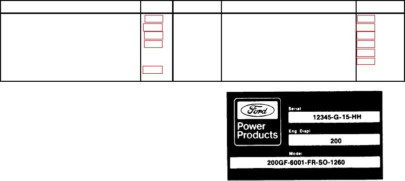
An Identification Decal (Figure 1) is affixed to the left side
of the rocker cover of each engine. The decal contains the
engine serial number which identifies this unit from all
others. Next is the engine displacement which determines
the engine specifications, then the model number and
S.O. or special options which determines the parts or
components required on this unit. Use all numbers when
seeking information or ordering replacement parts for this
engine.
DESCRIPTION
FIG. 1 Identification Decal
The Ford 200 cubic inch six-cylinder engines are
available as engine assemblies.
The aluminum alloy piston has three rings, two
These six-cylinder engines are the latest in engine
compression and one oil control. The auto thermic cam-
design from Ford Motor Company and they incorporate
ground pistons give longer life with a minimum of
many features for smooth, powerful operation, long life,
maintenance. The connecting rods are forged steel and
and a minimum of service.
use replaceable copper-lead bearings.
The cylinder block is manufactured from cast iron
The camshaft is supported by four bearings pressed
using the Ford-pioneered precision casting process. This
into the block. It is driven by gears from the crankshaft.
process provides ultra-lightweight design with a maximum
Camshaft end play is controlled by a plate bolted to the
of strength and rigidity. Special design features of the
front of the cylinder block.
cylinder block include seven main bearings and full-
The distributor, located on the left side of the engine,
length, full-circle water jackets. The seven main bearings
is driven by a gear on the camshaft and, in turn, drives the
provide a rugged 'foundation" for extra durability and a
rotor-type oil pump through an intermediate driveshaft.
smoothness of operation comparable to many V-8s. The
The cylinder head assembly contains the fuel intake
full-length, full-circle water jackets help eliminate hot-spots
and exhaust passages, the valves, the valve guides, and
and provide more uniform cylinder wall expansion under
the valve rocker arm assemblies. The valve guides are an
heavy-duty operation.
integral part of the cylinder head. The intake and exhaust
The precision-molded, cast-alloy iron crankshaft is
valves are actuated through the hydraulic valve lifters and
carried in seven replaceable copper-lead alloy main
rocker arms.
bearings. Crankshaft end thrust is controlled by the
An exhaust-heated section of the intake manifold
flanges of the No.
provides the heat to vaporize the incoming fuel charge
5 main bearing.
until the engine reaches operating temperature.
1-02