
Basic Engine
pump before the oil enters the engine. A valve, integral
A pressure lubrication system is maintained by a rotor
with the filter, provides a bypass to an oil gallery, if the
type oil pump mounted in the crankcase. Oil is pumped
filter should become clogged.
from the oil pan sump at the rear of the oil pan through
passages to the bearings and other engine components.
These engines are equipped with a crankcase ventilation
A spring-loaded relief valve in the pump limits the
system that vents crankcase fumes through two vented oil
maximum pressure in the system. A full-flow filter cleans
fill caps on the rocker arm cover.
the entire output of the
FIG 2 Engine Assembly
DIAGNOSIS AND TESTING CAMSHAFT LOBE LIFT
Check the lobe lift in consecutive order and make a note
of the readings.
I. Remove the air cleaner and valve rocker arm cover.
2. Remove the valve rocker arm shaft assembly as
detailed in Removal and Installation. Install a solid tappet-
type push rod in the push rod bore of the camshaft lobe to
be checked or use an adapter for ball end push rods.
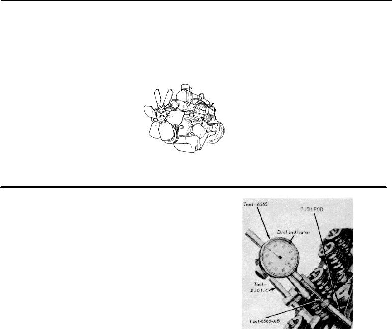
3. Make sure the push rod is in the valve lifter socket.
Install a dial indicator in such a manner as to have the ball
socket adapter of the indicator on the end of the push rod
in the same plane as the push rod movement (Figure 3).
4. Connect an auxiliary starter switch in the starting circuit.
Crank the engine with the ignition switch OFF.
Bump the crankshaft over until the tappet or lifter is on the
base circle of the camshaft lobe. At this point, the push
rod will be in its lowest position.
FIG. 3 Testing Camshaft Lobe Lift Typical
5. Zero the dial indicator. Continue to rotate the crankshaft
slowly until the push rod is in the fully raised position
COMPRESSION TEST COMPRESSION GAUGE CHECK
(highest indicator reading).
6. Compare the total lift recorded on the indicator with
specifications.
1. Be sure the crankcase is at the proper level and the
7. To check the accuracy of the original indicator reading,
battery is properly charged. Operate the engine for a
continue to rotate the crankshaft until the indicator reads
minimum of 30 minutes at 1200 rpm or until the engine is
zero. If the lift on any lobte l below specified wear limits,
at normal operating temperature. Turn the ignition switch
the camshaft and the valve lifters operating on the worn
off; then remove all the spark plugs.
lobe(s) must be replaced.
8. Remove the dial indicator and auxiliary starter switch.
9. Install the rocker arm shaft assembly as detailed under
Removal and Installation.
10. Install the valve rocker arm cover and the air cleaner.
1-03