
2
Set the carburetor throttle plates and choke plate in
HYDRAULIC VALVE LIFTER
the wide open position.
Dirt. deposits of gum and varnish and air bubbles in
3. Install a compression gauge in No 1 cylinder.
the lubricating oil can cause hydraulic valve lifter failure or
4. Install an auxiliary starter switch in the starting circuit
malfunction Dirt, gum and varnish can keep a check valve
Using the auxiliary-y starter switch. crank the engine
from seating and cause a loss of hydraulic pressure. An
(with the ignition switch OFF) at least five
open valve disc will cause the plunger to force oil back
compression strokes and record the highest reading.
into the valve lifter reservoir during the time the push rod
Note the approximate number of compression strokes
is being lifted to force the valve from its seat.
required to obtain the highest reading
Air bubbles in the lubricating system can be caused
5. Repeat the test on each cylinder as was required to
by too much oil in the system or too low an oil level. Air
obtain the highest reading on the No. 1 cylinder.
may also be draw, in into the lubricating system through
TEST CONCLUSION
an opening in a damaged oil pick-up tube Air in the
hydraulic system can cause a loss of hydraulic pressure.
The indicated compression pressures are considered
Assembled valve lifters can he tested with Tool 6500-
normal if the lowest reading cylinder is within 75'; of the
E to check the leak-down rate The leak-down rate
highest Refer to the following example and Figure
specification is the time in seconds for the plunger to
4.Seventy.-five percent of 140 the highest cylinder
move the length of Its travel while under a 50 Ib. load Test
reading, is 105 Therefore, cylinder No 7 being less than
the valve lifters as follows:
75%' of cylinder No 3 indicates an improperly seated valve
1. Disassemble and clean the lifter to remove all traces
or worn or broken piston rings. If one more cylinders read
of engine oil Lifters cannot be checked with engine oil
low. squirt approximately one 1 tablespoon of engine oil
in them Only the testing fluid can be used
on top of the pistons In the low reading cylinders Repeat
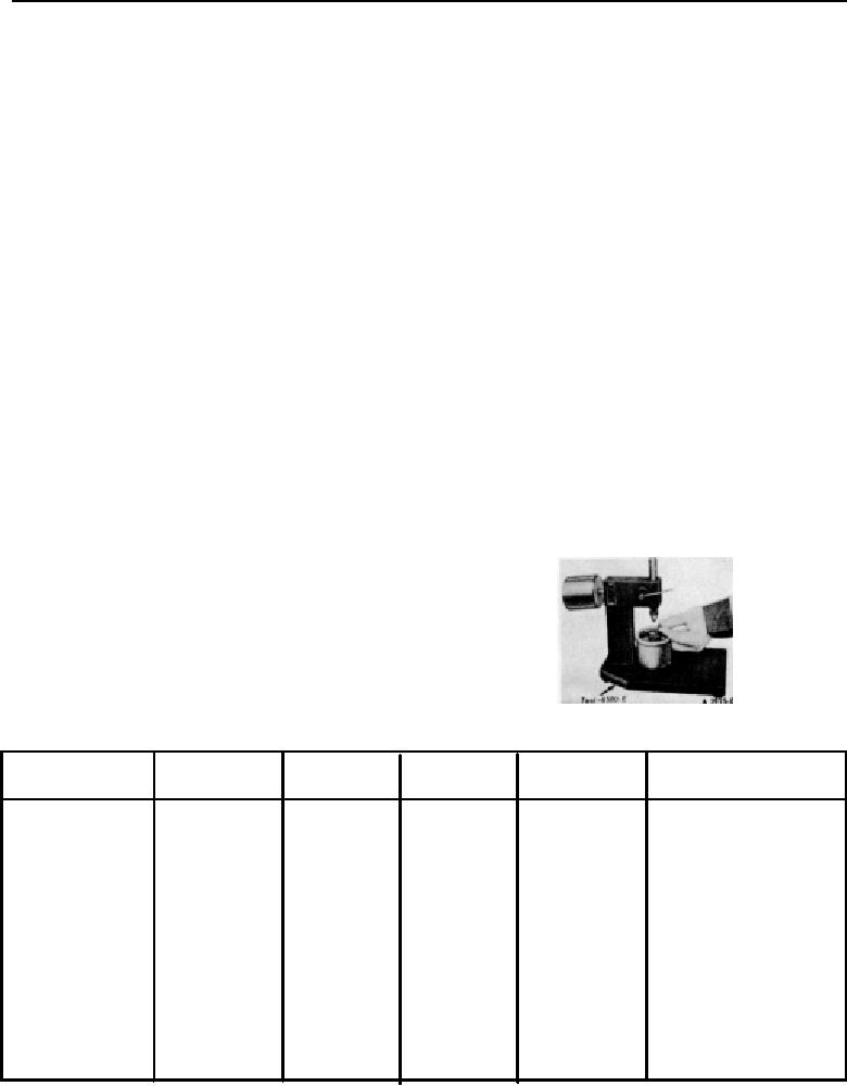
2. Place the valve lifter in the tester with the plunger
compression pressure check on these cylinders
facing upward. Pour hydraulic tester fluid into the cup
1. If compression improves considerably the piston rings
to a level that will cover the valve lifter assembly The
are at fault.
fluid can be purchased from the manufacturer of the
2. If compression does not improve, valves are sticking
tester Do not use kerosene. for it will not provide an
or seating poorly.
accurate test
3. If two adjacent cylinders indicate low compression
3. Place a 5/16 inch steel ball in the plunger cup (Figure
pressures and squirting oil on the pistons does not
5).
increase the compression. the cause may he at
4. Adjust the length of the ram so that the pointer is 1/16
cylinder head gasket leak between the cylinders.
Inch below the starting mark when the ram contacts
Engine oil and/or coolant in the cylinders could result
the valve lifter plunger (Figure 5) to facilitate timing as
from this problem.
the pointer passes the start timing mark.
It is recommended that the following quick reference
chart be used when checking cylinder compression
pressures. The chart has been calculated so that the
lowest reading number is 75'7 of the highest reading.
EXAMPLE
After checking the compression pressures in all
cylinders, it was found that the highest reading obtained
was 196 psi. The lowest pressure reading was 155 psi.
The engine is within specifications and the compression is
considered satisfactory.
FIG 5. Placing Steel Ball in Valve Lifter Plunger
Maximum
Minimum
Maximum
Minimum
Maximum
Minimum
PSI
PSI
PSI
PSI
PSI
PSI
134
101
174
131
214
160
136
102
176
132
216
162
138
104
178
'33
218
163
140
105
180
135
220
165
142
107
182
136
222
166
144
108
184
138
224
168
146
110
186
140
226
169
148
111
188
141
228
171
150
113
190
142
230
172
152
114
192
144
232
174
154
115
194
145
234
175
156
117
196
147
236
177
158
118
198
148
238
178
160
120
200
150
240
180
162
121
202
151
242
181
164
123
204
153
244
183
166
124
206
154
246
184
168
126
208
156
248
186
170
127
210
157
250
187
172
129
212
158
FIG. 4 Quick Reference Compression Pressure Limit Char
CA1005-A
1-04