
TM 5-3805-296-23-6
0388
DISASSEMBLY CONTINUED
NOTE
Note position of nuts and cam to aid in installation.
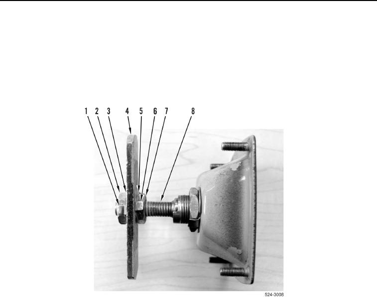
14. Bend locking tabs (Figure 12, Items 1 and 6) away from nuts (Figure 12, Items 2 and 7).
15. Remove nut (Figure 12, Item 2), washer (Figure 12, Item 3), cam (Figure 12, Item 4), washer
(Figure 12, Item 5), and nut (Figure 12, Item 7) from shaft (Figure 12, Item 8).
Figure 12. Latch Cam.
0388