
TM 5-3805-296-23-6
0373
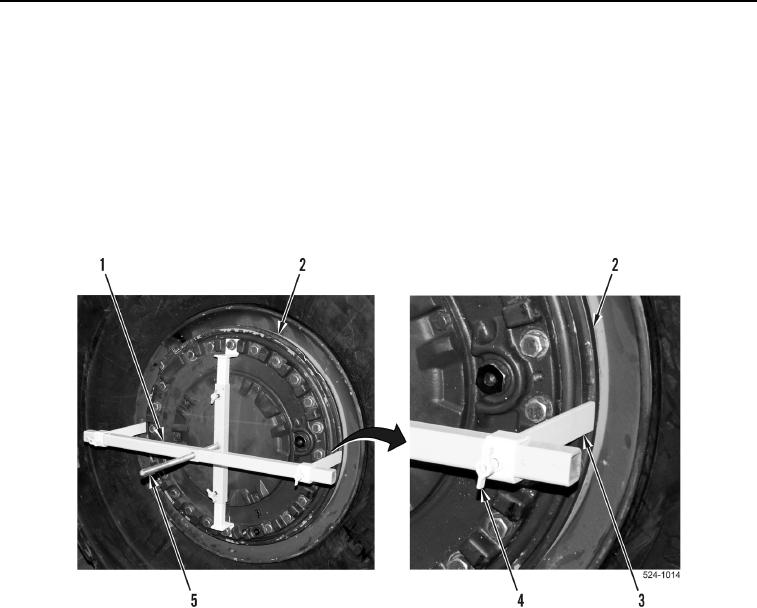
REMOVAL CONTINUED
26. Install crossmember (Figure 7, Item 1) on threaded rod (Figure 7, Item 5).
NOTE
Lockring compressor is supplied with two sets of extension legs. Use longer set of
extension legs in this procedure.
27. Install two extension legs (Figure 7, Item 3) on crossmember (Figure 7, Item 1).
28. Position two extension legs (Figure 7, Item 3) on outer edge of flange (Figure 7, Item 2) and tighten two
thumbscrews (Figure 7, Item 4).
Figure 7. Crossmember and Extension Legs.
0373