
TM 5-3805-296-23-6
0373
REMOVAL CONTINUED
NOTE
Install center bar on wheel using bolts adjacent to and directly opposite valve stem.
Install center bar on wheel using bolts removed from wheel.
Lockring compressor is supplied with two sets of center bar extensions. Use set of center
bar extensions with an offset and bolt holes in this procedure.
Rotate tire so center bar is oriented as shown.
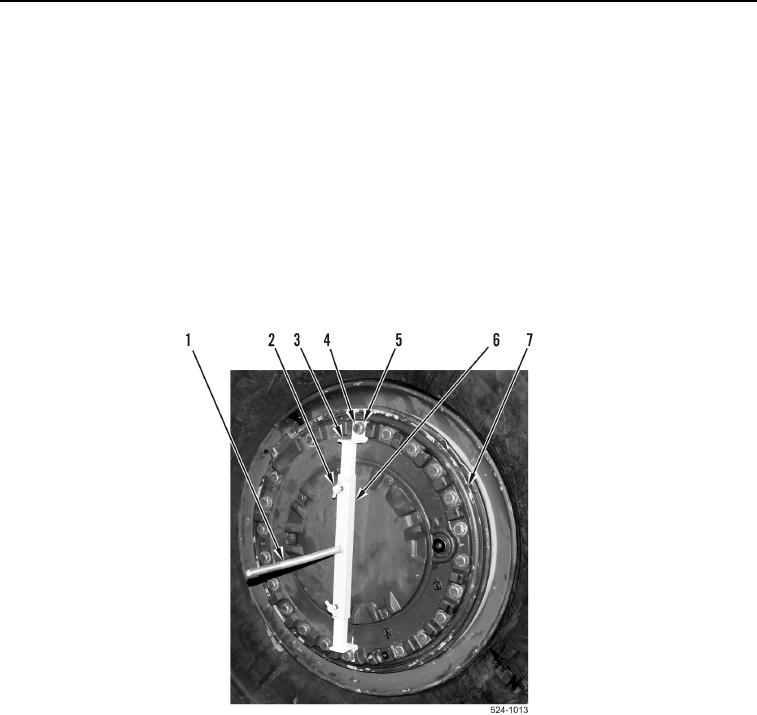
23. Remove two bolts (Figure 6, Item 4) and washers (Figure 6, Item 5) from wheel (Figure 6, Item 7).
24. Install center bar (Figure 6, Item 6), two washers (Figure 6, Item 5), and bolts (Figure 6, Item 4) on wheel
(Figure 6, Item 7).
25. Adjust center bar (Figure 6, Item 6) on center bar extensions (Figure 6, Item 3) to center threaded rod
(Figure 6, Item 1) on wheel (Figure 6, Item 7) and tighten two thumbscrews (Figure 6, Item 2).
Figure 6. Bolts and Center Bar.
0373