
TM 5-3805-296-23-5
0372
REMOVAL CONTINUED
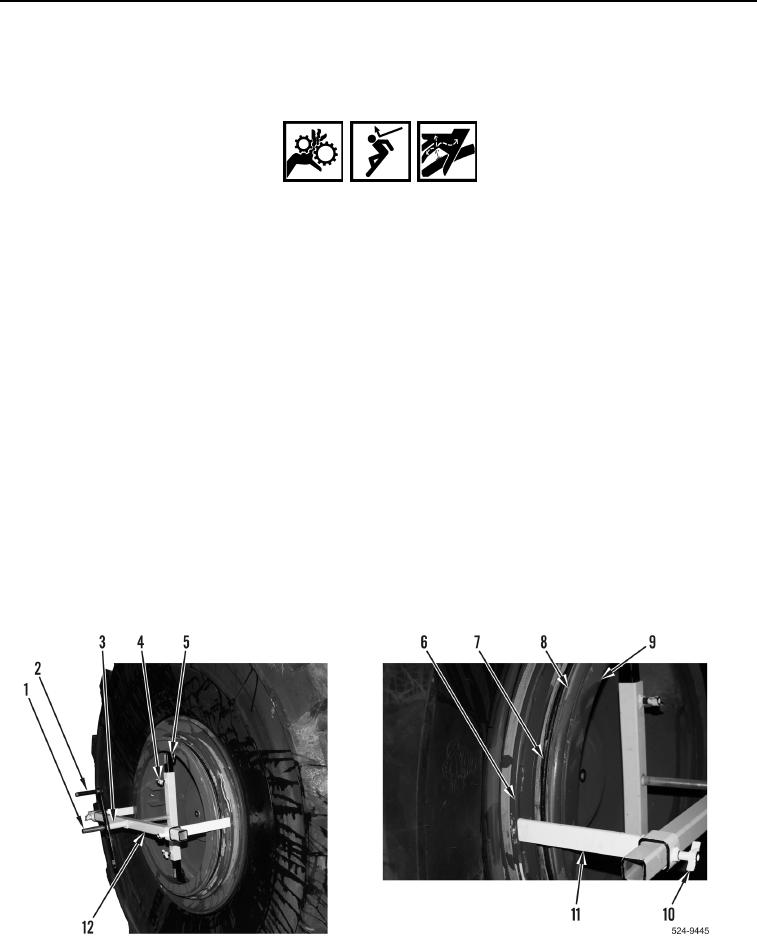
30. Slowly rotate handle (Figure 8, Item 2) clockwise to press flange (Figure 8, Item 6) inward until O-ring
(Figure 8, Item 7) is accessible.
WARNING
Use caution when removing lockring and O-ring from wheel. Lockring compressor and
flange are under pressure. Bumping or knocking extension legs or crossmember can
cause lockring compressor to dislodge from wheel assembly.
Keeps hands clear of lockring compressor and tire/wheel assembly. If lockring compressor
becomes dislodged, lockring compressor and flange will move rapidly.
Failure to follow these warnings may result in injury to personnel.
NOTE
When removing lockring from wheel, begin prying lockring at split. Using two lockring bars,
work around lockring to remove from wheel.
31. Using two lockring bars and assistance, remove lockring (Figure 8, Item 8) from wheel (Figure 8, Item 9).
32. Using screwdriver, remove O-ring (Figure 8, Item 7) from wheel (Figure 8, Item 9). Discard O-ring.
33. Rotate handle (Figure 8, Item 2) counterclockwise to release flange (Figure 8, Item 6).
34. Remove handle (Figure 8, Item 2) and spacer (Figure 8, Item 3) from threaded rod (Figure 8, Item 1).
35. Loosen two thumbscrews (Figure 8, Item 10) and remove two extension legs (Figure 8, Item 11) from
crossmember (Figure 8, Item 12).
36. Remove crossmember (Figure 8, Item 12) from threaded rod (Figure 8, Item 1).
37. Loosen two thumbscrews (Figure 8, Item 4) and remove center bar (Figure 8, Item 5) from wheel
(Figure 8, Item 9).
Figure 8. Lockring and O-Ring.
0372