
TM 5-3805-296-23-5
0345
ADJUSTMENT
000345
WARNING
Wheels must remain chocked during adjustment procedure. Failure to follow this warning
may result in injury or death to personnel.
NOTE
This procedure is for right rear brake actuator and slack adjuster. Follow same steps for
left rear brake actuator and slack adjuster.
1. Start engine and allow air tanks to charge. Do not apply parking brake (TM 5-3805-296-10).
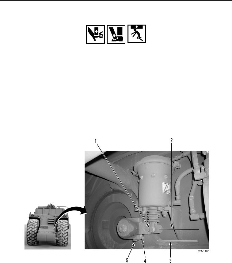
2. With assistance, measure movement of pin (Figure 7, Item 1) from brakes not applied position
(Figure 7, Item 2) to brakes applied position (Figure 7, Item 3).
3. Movement of pin (Figure 7, Item 1) should be 1.622.5 in. (41.164 mm).
4. Rotate worm bolt (Figure 7, Item 5) to obtain proper adjustment.
5. Tighten lock bolt (Figure 7, Item 4) after adjustment.
6. Apply parking brake and stop engine (TM 5-3805-296-10).
Figure 7. Actuator Adjustment.
0345
END OF TASK