
TM 5-3805-296-23-5
0340
DISASSEMBLY
000340
NOTE
Note orientation of fittings to aid in installation.
Note quantity and location of tiedown straps.
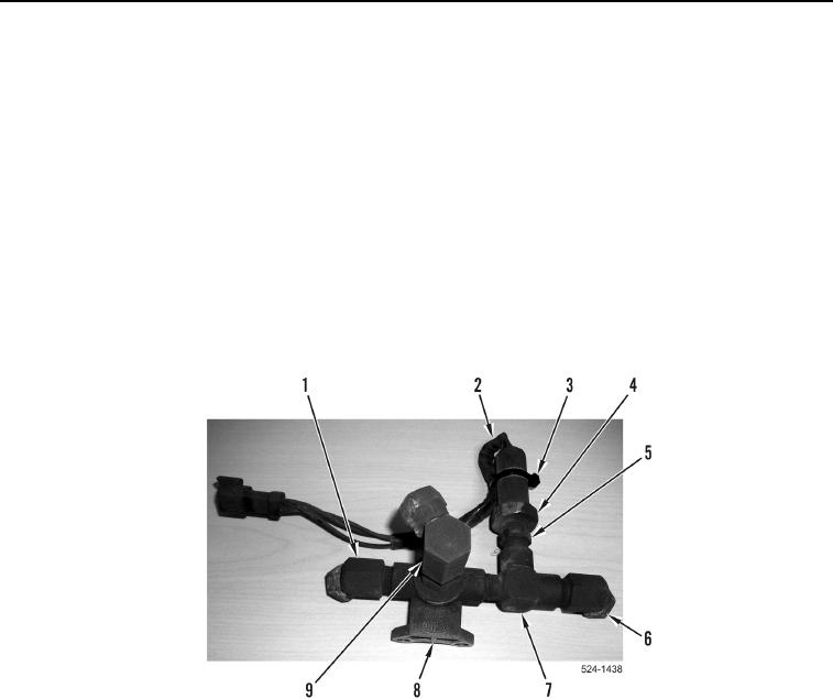
1. Remove tiedown strap (Figure 3, Item 3) from sensor wiring harness (Figure 3, Item 2) and sensor
(Figure 3, Item 4). Discard tiedown strap.
2. Remove sensor (Figure 3, Item 4) from fitting (Figure 3, Item 5).
3. Remove fitting (Figure 3, Item 5) from T-fitting (Figure 3, Item 7).
4. Remove fitting (Figure 3, Item 6) from T-fitting (Figure 3, Item 7).
5. Remove T-fitting (Figure 3, Item 7) from rear quick-release holding valve (Figure 3, Item 8).
6. Remove fitting (Figure 3, Item 9) from rear quick-release holding valve (Figure 3, Item 8).
7. Remove fitting (Figure 3, Item 1) from rear quick-release holding valve (Figure 3, Item 8).
Figure 3. Rear Quick-Release Holding Valve Fittings.
0340
END OF TASK
CLEANING AND INSPECTION
000340
Clean and inspect all components IAW Mechanical General Maintenance Instructions (WP 0539).
END OF TASK