
TM 5-3805-296-23-5
0320
REMOVAL CONTINUED
CAUTION
Cap or plug hydraulic hose and hydraulic tank return tube to prevent contamination.
Failure to follow this caution may result in equipment damage.
NOTE
Tag and mark hydraulic hose to aid in installation.
Note routing of hydraulic hose to aid in installation.
Use a container to catch any fluid that may drain from system. Dispose of fluid IAW local
policy and ordinances. Ensure all spills are cleaned up.
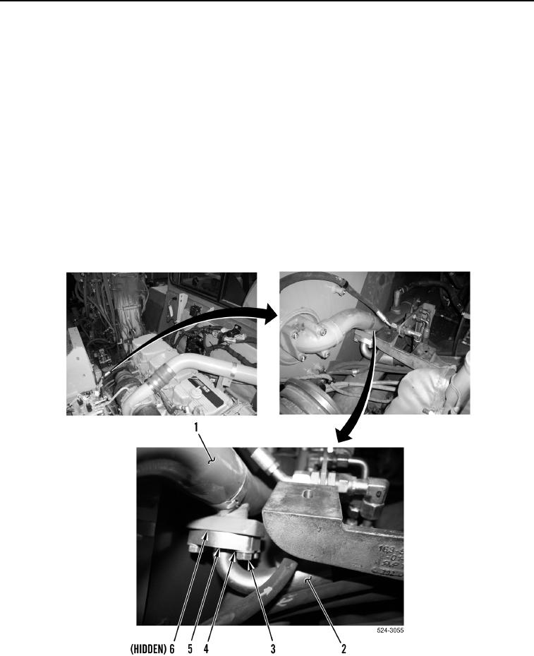
17. Remove four bolts (Figure 4, Item 3), washers (Figure 4, Item 4), two flange halves (Figure 4, Item 5), and
hydraulic hose (Figure 4, Item 2) from hydraulic tank return tube (Figure 4, Item 1).
18. Remove O-ring (Figure 4, Item 6) from hydraulic hose (Figure 4, Item 2). Discard O-ring.
19. Remove hydraulic hose (Figure 4, Item 2) from machine.
Figure 5. Hydraulic Hose and Hydraulic Tank Return Tube.
0320