
TM 5-3805-296-23-5
0309
NATO SLAVE RECEPTACLE CABLE INSTALLATION
000309
WARNING
Make sure battery disconnect switch is in OFF position before replacing NATO slave
receptacle and cables. Failure to follow this warning may result in injury or death to
personnel or damage to equipment.
NOTE
Route and install cables as noted during removal.
1. Install cable (Figure 13, Item 6) on junction block terminal (Figure 13, Item 2).
2. Install cable (Figure 13, Item 5) on junction block terminal (Figure 13, Item 2).
3. Install washer (Figure 13, Item 4) and nut (Figure 13, Item 3) on junction block terminal (Figure 13, Item 2).
4. Position cover (Figure 13, Item 1) on junction block terminal (Figure 13, Item 2).
NOTE
Route and install cables as noted during removal.
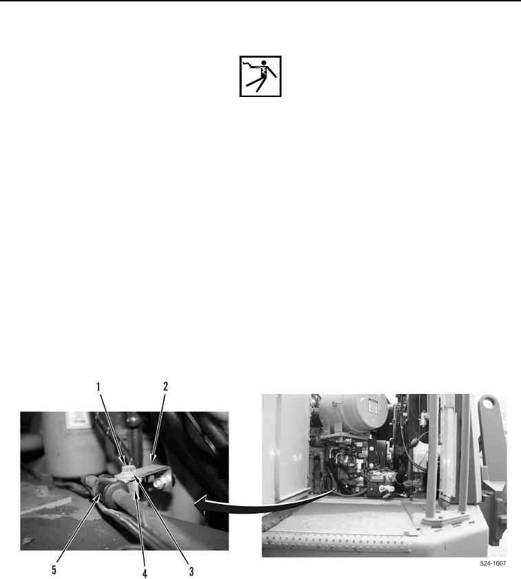
5. Position P-clamp (Figure 14, Item 5) on boss (Figure 14, Item 4).
6. Position bracket (Figure 14, Item 2) on boss (Figure 14, Item 4).
7. Install washer (Figure 14, Item 3) and bolt (Figure 14, Item 1) on boss (Figure 14, Item 4).
Figure 14. NATO Slave Receptacle Cable P-clamp.
0309