
TM 5-3805-296-23-2
0104
Table 1. Engine Will Not Crank Continued.
0104
MALFUNCTION
TEST OR INSPECTION
CORRECTIVE ACTION
Engine WIll Not Crank
4. Turn battery disconnect switch and
Continued
ignition switch to ON position
(TM 5-3805-296-10).
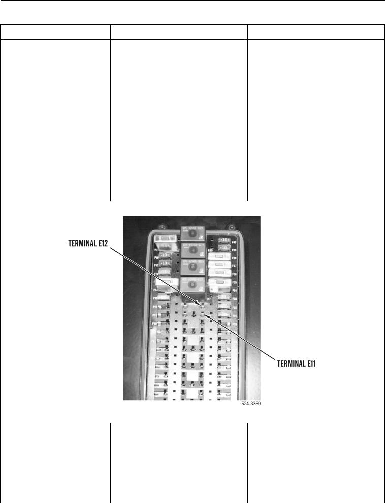
5. Using digital multimeter
Voltage 18 to 25 V Proceed to step 6.
Voltage Less Than 18 V Replace
(WP 0540), test for voltage
between terminal E12 (Figure 5)
fuse panel wiring harness (WP 0515).
and ground.
Proceed to Test Step 27.
6. Using digital multimeter
Voltage 18 to 25 V Turn ignition
(WP 0540), test for voltage
switch and battery disconnect switch to
between terminal E11 (Figure 5)
OFF position (TM 5-3805-296-10).
and ground while assistant turns
Proceed to Test Step 7.
ignition switch to start engine
Voltage Less Than 18 V Turn ignition
(TM 5-3805-296-10).
switch and battery disconnect switch to
OFF position (TM 5-3805-296-10).
Install start relay on circuit breaker
panel.
Proceed to Test Step 16.
Figure 5. Testing Voltage to Start Relay.
0104