
TM 5-3805-296-23-2
0100
Table 1. 0821 Display Power Supply Diagnostic Codes Continued.
0100
CID FMI
TEST OR INSPECTION
CORRECTIVE ACTION
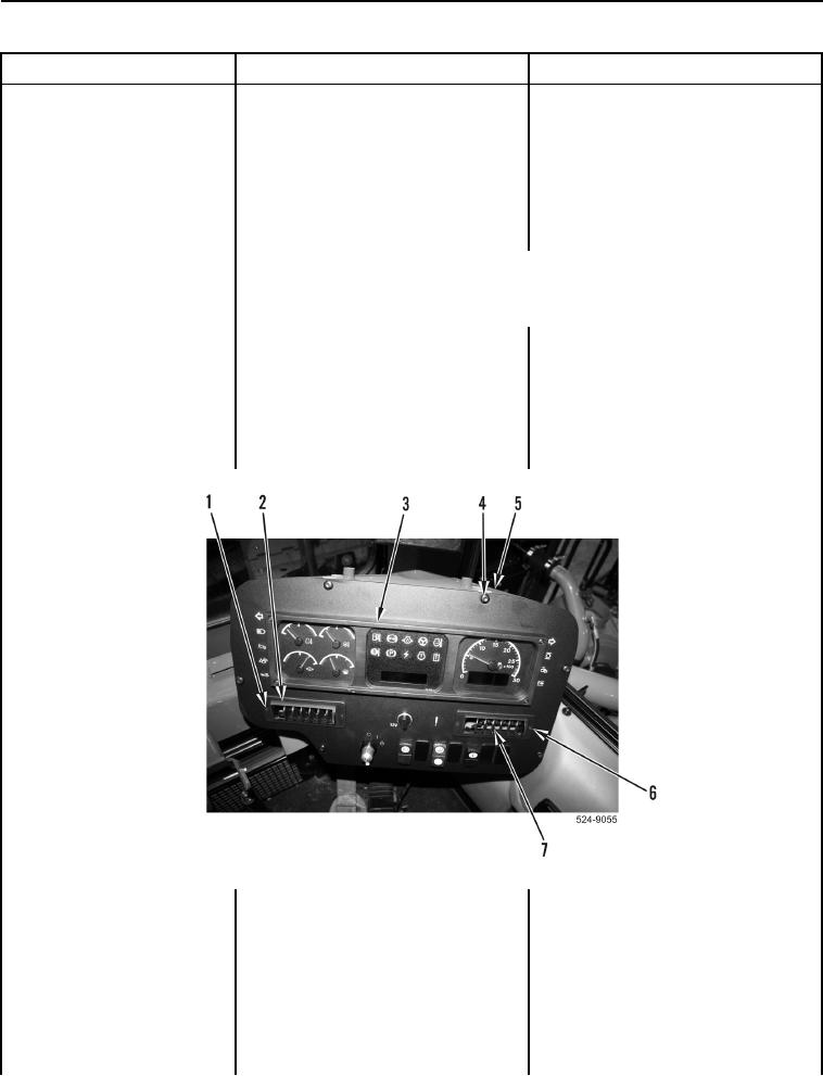
3. Remove two bolts
0821-03 Display Power
(Figure 2, Item 1) and left vent
Supply Voltage Above
(Figure 2, Item 2) from instrument
Normal Continued
panel (Figure 2, Item 3).
4. Remove two bolts
(Figure 2, Item 6) and right vent
(Figure 2, Item 7) from instrument
panel (Figure 2, Item 3).
NOTE
DO NOT disconnect connector P-C1 (WP 0012, Figure 253) from W-C7
(WP 0012, Figure 252).
5. Remove six bolts (Figure 2, Item 4)
from instrument panel
(Figure 2, Item 3) and ROPS
(Figure 2, Item 5). Position
instrument panel to access
connector P-C19
(WP 0012, Figure 270).
Figure 2. Instrument Panel and Retaining Hardware.
0100