
TM 5-3805-296-23-2
0096
Table 1. 0263 Sensor Power Supply Diagnostic Codes - Continued.
0096
CID FMI
TEST OR INSPECTION
CORRECTIVE ACTION
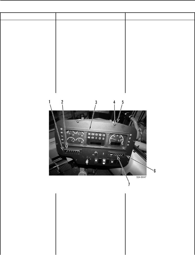
2. Remove two bolts
0263-04 Digital Sensor
(Figure 4, Item 1) and left vent
Power Supply (8V or 12V)
(Figure 4, Item 2) from instrument
Voltage Below Normal
panel (Figure 4, Item 3).
Continued
3. Remove two bolts
(Figure 4, Item 6) and right vent
(Figure 4, Item 7) from instrument
panel (Figure 4, Item 3).
4. Remove six bolts (Figure 4, Item 4)
from instrument panel (Figure 4,
Item 3) and ROPS
(Figure 4, Item 5). Position
instrument panel to access
connector P-C18
(WP 0012, Figure 269).
Figure 4. Instrument Panel and Retaining Hardware.
0096