
TM 5-3805-296-23-1
0037
Table 1. 0562 Module Communication Diagnostic Codes Continued.
037
CID FMI
TEST OR INSPECTION
CORRECTIVE ACTION
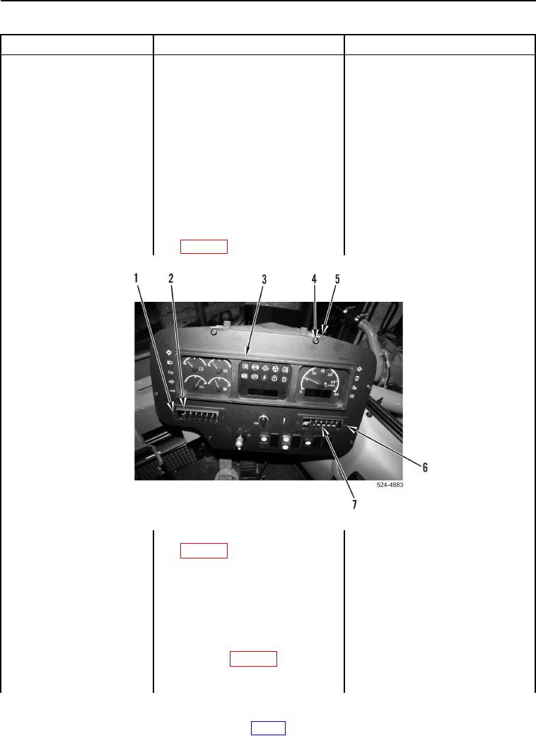
3. Remove two bolts
0562-09 Caterpillar
(Figure 2, Item 1) and left vent
Monitoring System
(Figure 2, Item 2) from instrument
Abnormal Update Rate
panel (Figure 2, Item 3).
Continued
4. Remove two bolts
(Figure 2, Item 6) and right vent
(Figure 2, Item 7) from instrument
panel (Figure 2, Item 3).
5. Remove six bolts (Figure 2, Item 4)
from instrument panel
(Figure 2, Item 3) and ROPS
(Figure 2, Item 5). Position
instrument panel to
access connector P-C18
(WP 0012, Figure 269).
Figure 2. Instrument Panel and Retaining Hardware.
0037
6. Disconnect connector P-C18
(WP 0012, Figure 269) from tractor
operator monitor.
7. Turn battery disconnect switch and
ignition switch to ON position
(TM 5-3805-296-10).
8. Using digital multimeter
Voltage 18 to 25 V Proceed to Test
(WP 0540), test for voltage
Step 2.
between connector P-C18
Voltage Less Than 18 V Proceed to
terminal 1 (WP 0012, Figure 269)
Test Step 5.
and ground.