
TM 3-4240-302-30&P-1
LOCATION
ITEM
ACTION
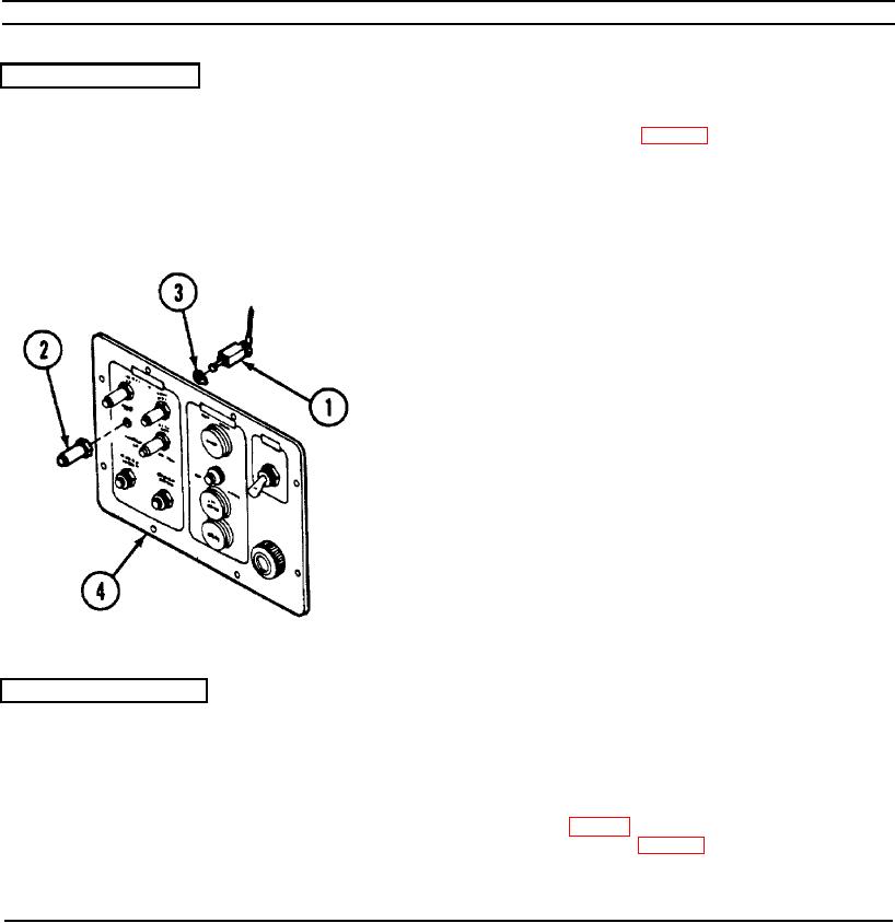
REMOVAL
MAIN FAN circuit
1. Disassemble CCM (p. 2-77).
breaker CB7
2. Remove and tag wire leads from MAIN
FAN circuit breaker CB7 (1).
3. Unscrew and remove waterproof boot (2), if
present.
4. Remove MAIN FAN circuit breaker CB7 (1)
and keying washer (3).
INSTALLATION
1. Insert MAIN FAN circuit breaker CB7 (1)
with keying washer (3) in panel (4) and
secure with waterproof boot (2), if
necessary.
2. Connect wire leads. Refer to wiring
diagram (p. 2-99).
3. Reassemble CCM (p. 2-77).
2-91