
TM 5-3805-296-23-6
0430
INSTALLATION CONTINUED
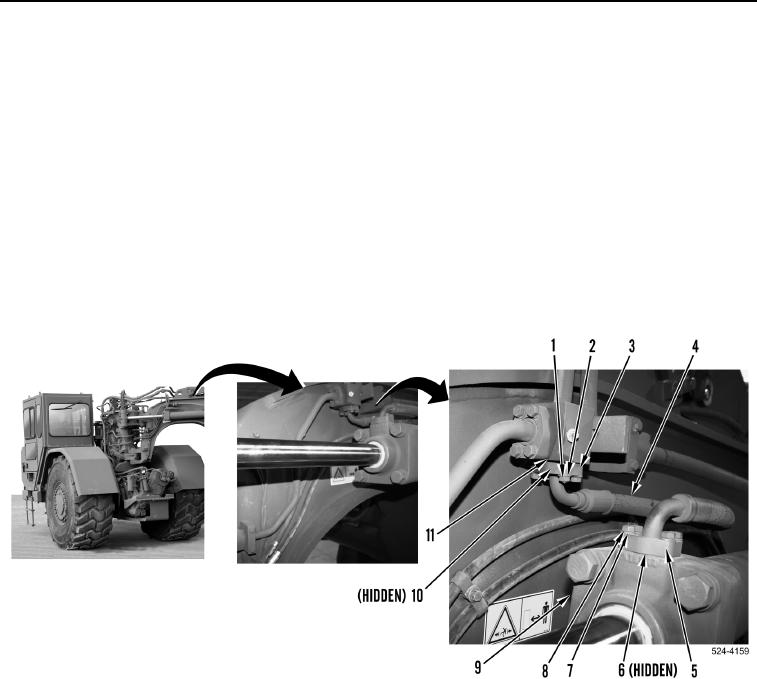
Rod End
000430
NOTE
Remove plugs and caps from hydraulic hoses and fittings.
Install hydraulic hoses as tagged during removal.
1. Position hydraulic line (Figure 17, Item 4) on machine.
2. Install new O-ring (Figure 17, Item 6) on hydraulic hose (Figure 17, Item 4).
3. Install hydraulic hose (Figure 17, Item 4), two flange halves (Figure 17, Item 5), four washers
(Figure 17, Item 7), and bolts (Figure 17, Item 8) on steering cylinder (Figure 17, Item 9).
4. Install O-ring (Figure 17, Item 10) on hydraulic hose (Figure 17, Item 4).
5. Install hydraulic hose (Figure 17, Item 4), two flange halves (Figure 17, Item 3), four washers
(Figure 17, Item 2), and bolts (Figure 17, Item 1) on hydraulic line (Figure 17, Item 11).
Figure 17. Rod End.
0430
END OF TASK