
TM 5-3805-296-23-6
0430
INSTALLATION CONTINUED
NOTE
Remove plugs and caps from hydraulic hoses and fittings.
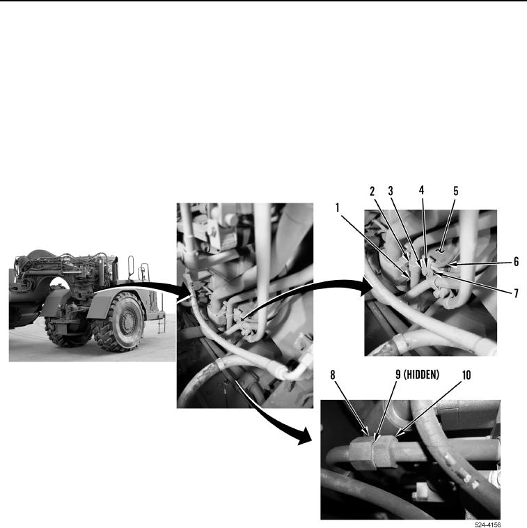
Install hydraulic hoses as tagged during removal.
5. Install new O-ring (Figure 22, Item 9) on hydraulic line (Figure 22, Item 1).
6. Connect hydraulic line (Figure 22, Item 10) to hydraulic line (Figure 22, Item 1), and tighten tube nut
(Figure 22, Item 8).
7. Install P-clamp (Figure 22, Item 7), lines (Figure 22, Item 6), P-clamp (Figure 22, Item 2), hydraulic line
(Figure 22, Item 1), washer (Figure 22, Item 4), and bolt (Figure 22, Item 3) on hitch (Figure 22, Item 5).
Figure 22. Line, Lower Connection.
0430
END OF TASK