
TM 5-3805-296-23-6
0430
INSTALLATION CONTINUED
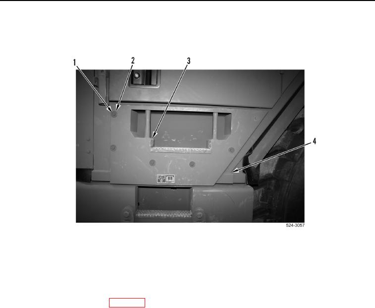
12. Install step (Figure 26, Item 3), six washers (Figure 26, Item 2) and bolts (Figure 26, Item 1) on cab
(Figure 26, Item 4).
Figure 26. Cab Step.
0430
END OF TASK
FOLLOW-ON TASKS
000430
1. Fill hydraulic system (WP 0325).
2. Raise left frame access plate (WP 0376).
3. Remove wheel chocks (WP 0454).
4. Verify correct operation of machine (TM 5-3805-296-10).
END OF TASK
END OF WORK PACKAGE
0430-31/(32 blank)