• Home
  • Download PDF
  • Order CD-ROM
  • Order in Print
Figure 14. Left Inboard Hose to Draft Frame Line Connection.
Figure 16. Right Side Draft Frame Clamp.

Field Maintenance Manual For Military 621G Scraper -6 Page Navigation
  751    752    753    754    755  756  757    758    759    760    761  
img
.
TM 5-3805-296-23-6
0419
INSTALLATION CONTINUED
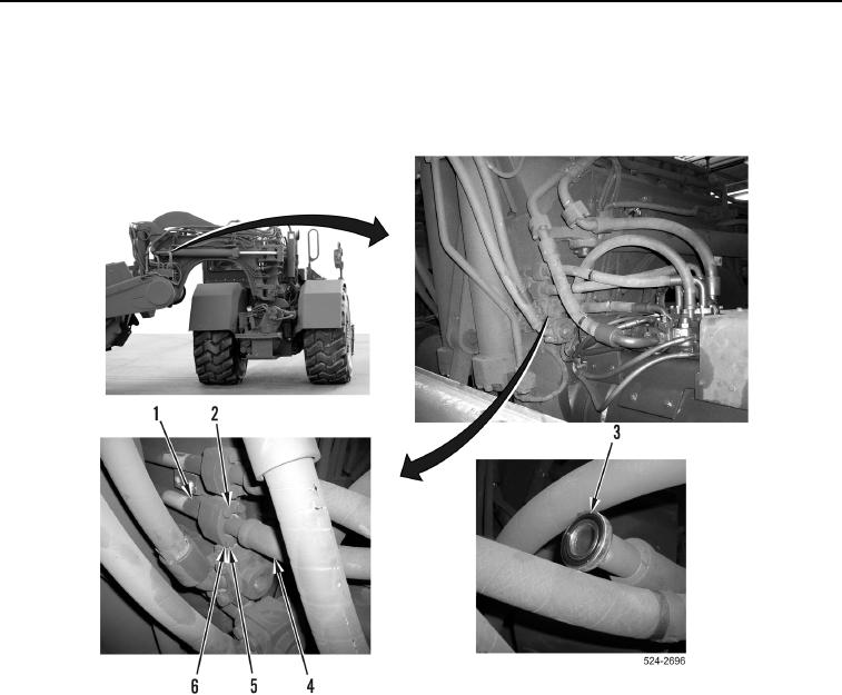
9. Install new O-ring (Figure 15, Item 3) on hydraulic hose (Figure 15, Item 4).
10. Install hydraulic hose (Figure 15, Item 4), two flange halves (Figure 15, Item 2), four washers
(Figure 15, Item 6), and bolts (Figure 15, Item 5) on hydraulic tube (Figure 15, Item 1).
Figure 15. Control Valve Hose to Draft Frame Line Connection.
0419
0419-17


Privacy Statement
Press Release
Contact

© Copyright Integrated Publishing, Inc.. All Rights Reserved.