
TM 5-3805-296-23-6
0419
INSTALLATION CONTINUED
NOTE
Remove plugs and caps from hydraulic hoses and fittings.
Install hydraulic hoses as noted during removal.
Install hydraulic hoses as tagged and marked during removal.
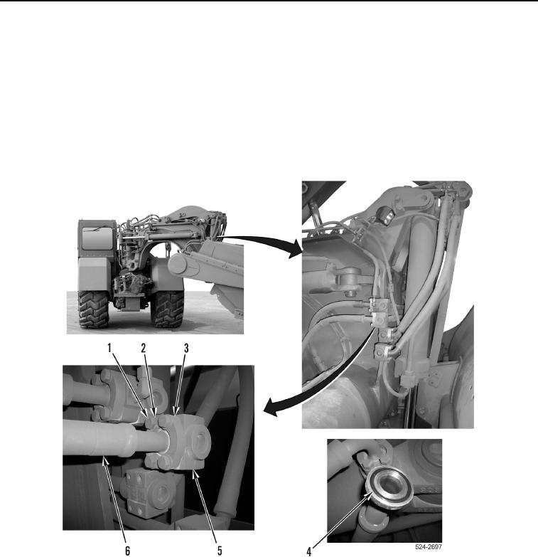
7. Install new O-ring (Figure 14, Item 4) on hydraulic hose (Figure 14, Item 6).
8. Using assistance, install hydraulic hose (Figure 14, Item 6), two flange halves (Figure 14, Item 3), four washers
(Figure 14, Item 2), and bolts (Figure 14, Item 1) on hydraulic line (Figure 14, Item 5).
Figure 14. Left Inboard Hose to Draft Frame Line Connection.
0419