Home
Download PDF
Order CD-ROM
Order in Print
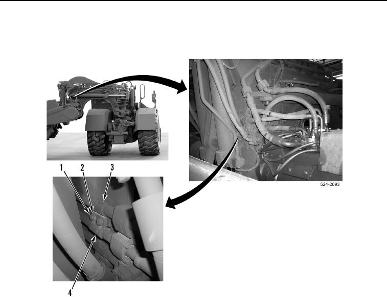
Figure 1. Main Control Valve Connection.
Figure 3. Left Side Draft Frame Clamp Bolts.
Field Maintenance Manual For Military 621G Scraper -6
Page Navigation
738
739
740
741
742
743
744
745
746
747
748
TM
5-3805-296-23-6
0419
REMOVAL
CONTINUED
3.
Remove
two
bolts
(Figure
2,
Item
1),
washers
(Figure
2,
Item
2),
clamp
(Figure
2,
Item
3),
and
clamp
(Figure
2,
Item
4) from
machine.
Figure 2. Right
Side
Draft
Frame
Clamp.
0419
0419-4