
TM 5-3805-296-23-6
0418
INSTALLATION CONTINUED
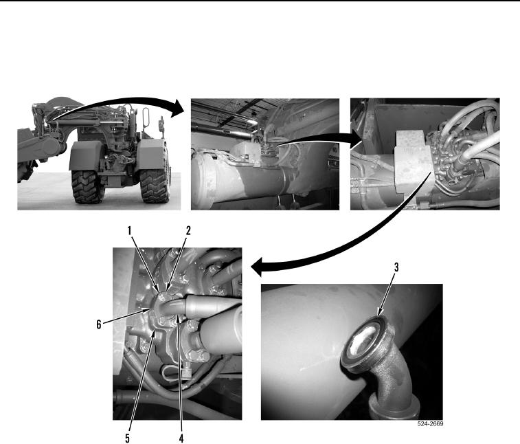
13. Install new O-ring (Figure 14, Item 3) on hydraulic hose (Figure 14, Item 4).
14. With assistance, install hydraulic hose (Figure 14, Item 4), two flange halves (Figure 14, Item 6), four washers
(Figure 14, Item 1), and bolts (Figure 14, Item 2) on rear main control valve (Figure 14, Item 5).
Figure 14. Main Control Valve Connection.
0418
END OF TASK
FOLLOW-ON TASKS
000418
1. Remove wheel chocks (WP 0454).
2. Verify correct operation of machine (TM 5-3805-296-10).
END OF TASK
END OF WORK PACKAGE