
TM 5-3805-296-23-6
0419
REMOVAL CONTINUED
WARNING
Allow hydraulic system to cool before performing procedure. Hot hydraulic fluid can cause
severe burns. Wear eye, hand, and skin protection when working with heated parts.
Hydraulic oil is very slippery. Immediately wipe up any spills. Failure to follow this warning
may result in injury or death to personnel.
CAUTION
Plug and cap all hydraulic hoses and fittings to prevent contamination.
NOTE
Tag and mark hydraulic hoses to aid in installation.
Note routing and location of hydraulic hoses to aid in installation.
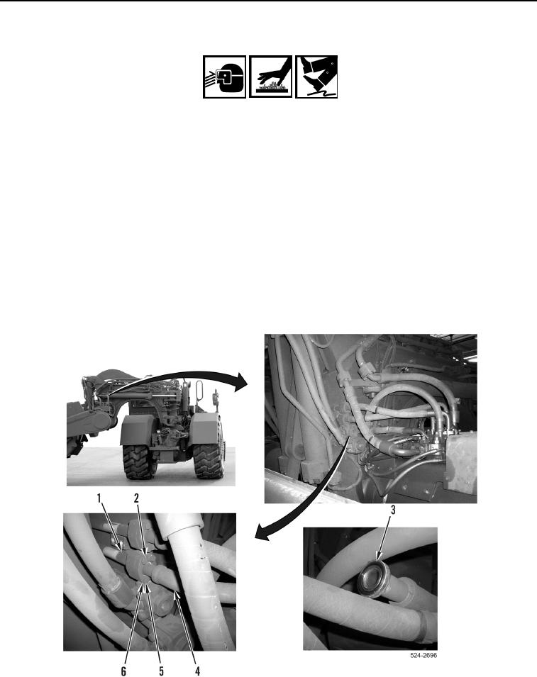
5. Remove four bolts (Figure 4, Item 5), washers (Figure 4, Item 6), two flange halves (Figure 4, Item 2), and
hydraulic hose (Figure 4, Item 4) from hydraulic line (Figure 4, Item 1).
6. Remove O-ring (Figure 4, Item 3) from hydraulic hose (Figure 4, Item 4). Discard O-ring.
Figure 4. Control Valve Hose to Draft Frame Line Connection.
0419