
TM 5-3805-296-23-6
0405
INSTALLATION CONTINUED
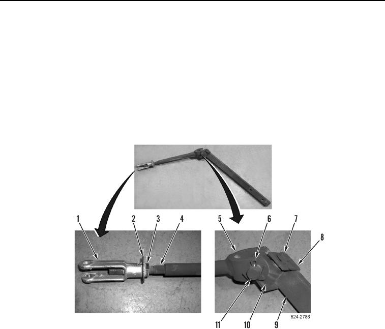
17. Install pivot block (Figure 25, Item 10), pivot pin (Figure 25, Item 7), and new cotter pin (Figure 25, Item 8) on
rod (Figure 25, Item 9).
18. Install rod (Figure 25, Item 5), pivot pin (Figure 25, Item 11), and new cotter pin (Figure 25, Item 6) on pivot
block (Figure 25, Item 10).
NOTE
Install jam nut as noted during removal.
19. Install jam nut (Figure 25, Item 3), washer (Figure 25, Item 2), and clevis (Figure 25, Item 1) on rod
(Figure 25, Item 4).
Figure 25. Spring Linkage.
0405