
TM 5-3805-296-23-6
0397
REMOVAL CONTINUED
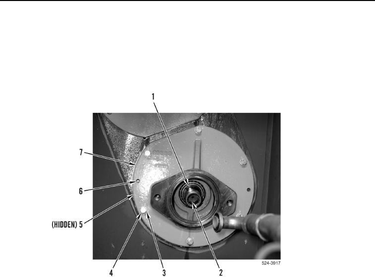
8. Remove sleeve (Figure 5, Item 1) and shaft (Figure 5, Item 2) from machine.
9. Remove six bolts (Figure 5, Item 4) and washers (Figure 5, Item 3) from adapter (Figure 5, Item 7).
10. Install two bolts (Figure 5, Item 4) in threaded holes (Figure 5, Item 6). Tighten bolts evenly and remove
adapter (Figure 5, Item 7) and O-ring (Figure 5, Item 5) from machine. Discard O-ring.
11. Remove two bolts (Figure 5, Item 4) from threaded holes (Figure 5, Item 6).
Figure 5. Shaft and Sleeve.
0397