
TM 5-3805-296-23-5
0350
INSTALLATION CONTINUED
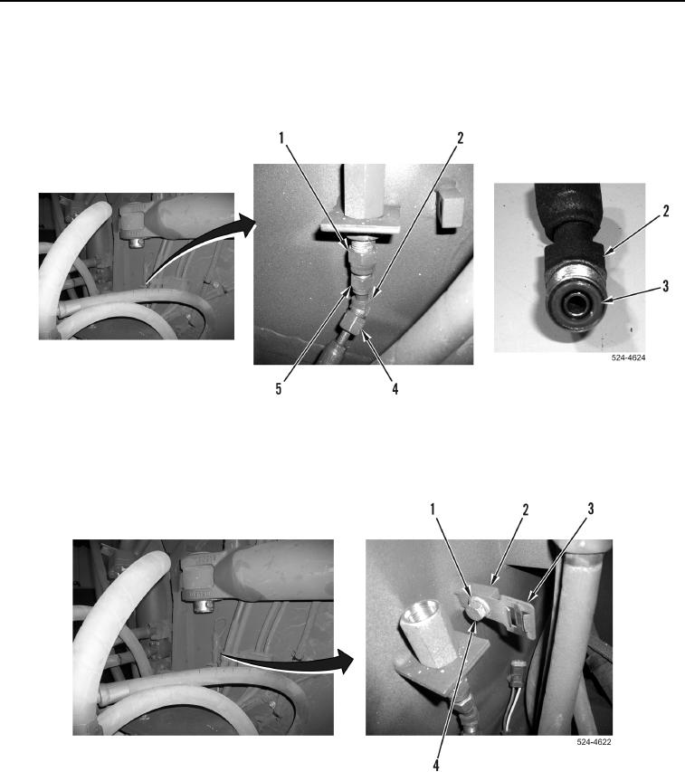
5. Install new O-ring (Figure 6, Item 3) on fitting (Figure 6, Item 2).
6. Install hydraulic hose (Figure 6, Item 4) on fitting (Figure 6, Item 2).
7. Install fitting (Figure 6, Item 2) on fitting (Figure 6, Item 1), and tighten jam nut (Figure 6, Item 5).
Figure 6. Hydraulic Hose.
0350
8. Install wiring harness bracket (Figure 7, Item 3), washer (Figure 7, Item 1), and bolt (Figure 7, Item 4) on
mounting boss (Figure 7, Item 2).
Figure 7. Wiring Harness Bracket.
0350